S225-10-5
1-5
CAUTION: When installing a regulator, solidly
ground both the regulator tank AND the control.
Failure to do so may cause damage to the regulator and/or
control due to current surges and may subject personnel
to electrical shock.
!
WARNING: Closing the bypass switch with
the tap changer off neutral will short circuit part
of the series winding. Before closing the bypass
switch, the regulator must be on NEUTRAL and the
control switch set to OFF.
!
Procedure A should be followed when one bypass switch
and two disconnect switches are used. Procedure B should
be followed when a regulator bypass-disconnect switch is
used.
Placing A Regulator Into Service
Regulators can be placed in service without interrupting
load continuity.
Figure 1-5.
Elevating structure.
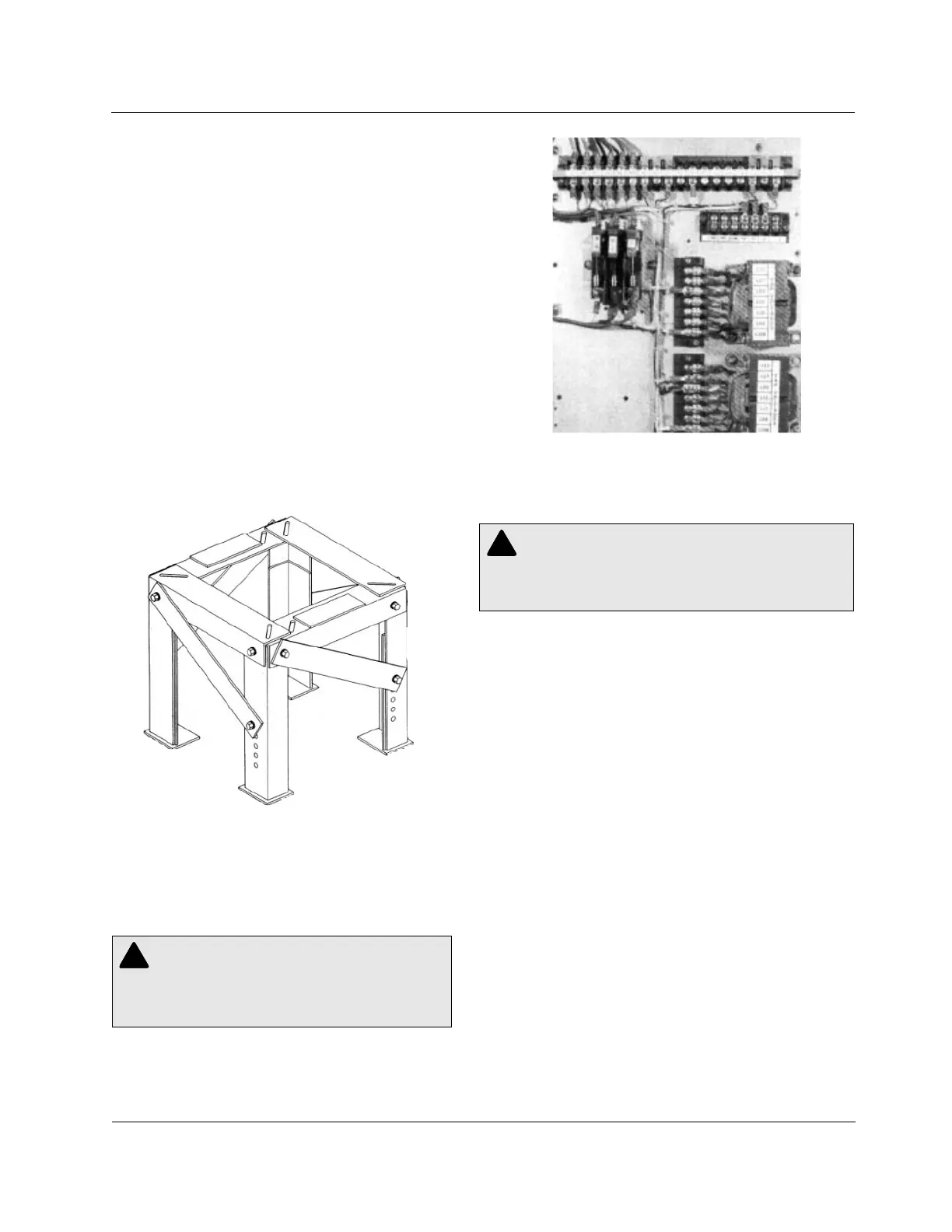
Figure 1-6.
Knife switches and TB1 (with optional V6 knife switch and
RCT2).
PROCEDURE A: ONE BYPASS SWITCH AND TWO
DISCONNECT SWITCHES
1. Verify from the regulator nameplate that the control circuit is
connected for the proper regulated load voltage.
2. Set the POWER switch to OFF and the CONTROL switch to
OFF.
3. The knife switches on the back panel should be set with the V1
(potential switch) [and V6 if present] closed (pushed in), and
the C (CT shorting switch) open (pulled out). See Figure 1 -5.
4. Close the SOURCE-LOAD (SL) disconnect switch. (Delta appli-
cations only).
5. Close the SOURCE (S) disconnect switch.
6. Set the POWER switch to INTERNAL and the CONTROL
switch to MANUAL.
7. Lift the RAISE-LOWER switch to operate the tap changer two
or three steps, then depress the RAISE-LOWER switch to
return the tap changer to neutral position. (These steps verify
the mechanism is functional.) When on neutral, the NEUTRAL
LAMP will glow and the position indicator will point to zero.
8. With the regulator in neutral position, set the CONTROL
switch to OFF, set the POWER switch to OFF, open the V1
knife switch (back panel) [and V6 if present], and remove the
6A motor fuse.
NOTE: Individual switches are shown for the bypass and
disconnect functions. However, a regulator-bypass-discon-
nect switch can be used in each phase to perform the
bypassing and disconnecting operations in sequence. Each
of these switches replaces one bypass and two disconnect
switches shown in the diagrams.
Mounting
A regulator can be mounted on a pole, cross arm platform,
or elevating structure (optional). Regulators are normally
provided with either pole mounting brackets or a station
platform according to the rating. This information is avail-
able in Table 3-1, page 3-1, by noting the S(Substation) suf-
fix to the kVA. A Cooper Power System's elevating structure
(Figure 1-4) can be used to simplify substation installation
of regulators requiring a specific live part-to-ground clear-
ance.
The regulator control can be mounted on the regulator
tank, or at a point remote from the unit. Rubber-covered
cable is available in lengths of 15, 20, 25, 30, and 35 ft for
interconnection between the control and the regulator.
A threaded stud is provided at the bottom of the control
enclosure and a ground pad is provided on the side of the
enclosure, for grounding purposes.