S225-10-5
3-1
Spring- and Direct-drive Tap Changers
Regulators for low-current applications employ stored-energy
spring-drive tap changers. Commonly, they are used on ratings
219 amps and below. The tap changer for a specific rating is
shown on the rating plate. Figures 3-1 (95 BIL) and 3-2 (150 BIL)
illustrate typical spring-drive mechanisms. on regulators manu-
factured January 1976 and later, the model number is stamped
on the drive frame. Common models are either 859 or 928
(Figure 3-1) and 170 (Figure 3-2), followed by a suffix letter.
Voltage regulators used in medium-and high-current applica-
tions employ direct-motor-driven tap changers. They have the
motor and gear train moving the contacts through a geneva gear,
pinion and scroll cam. Direct-drive tap changers are commonly
applied above 219 amps. Both the mid-current, Model 770B
(Figure 3-3) and high-current, Model 660C (Figure 3-4) are rated
150 BIL. See Table 3-1 for application chart of tap changer mod-
els.
MOTOR
The motor for the spring-drive tap changer is a capacitor-run,
reversing gear-motor suitable for operation at 120 volts ac, sin-
glephase, at 50/60-Hz. An integral braking mechanism controls
motor coast.
The motor for the direct-drive tap changers is a capacitor-start,
capacitor-run, high-torque, reversing, gear-motor rated 120 volts
ac, single-phase, at 50/60-Hz, with an internal magnetically dis-
engaging brake mechanism.
All components are compatible with hot transformer oil and the
windings are oil cooled. The motors will carry locked-rotor current
for at least 3000 hours.
REVERSING SWITCH
The reversing switch function changes the polarity of the tapped
winding. When the spring-drive tap changer is in the neutral posi-
tion, the reversing switch is open. When the direct-drive tap
changer is in the neutral position, the reversing movable contact
is in contact with the lower reversing stationary contact (VL).
The load current on all types is carried by the source bushing,
the reactor, slip rings, main movable contacts, neutral stationary
contact and the load bushing.
The reversing switch motion on the spring-drive tap changer
occurs as the main movable contacts enter or leave the neutral
position. A pin in the contact drive sprocket assembly engages a
slot in the reversing segment when the main switch is in the neu-
tral position. The first tap step in either direction rotates the seg-
ment and the reversing switch engages the appropriate reversing
stationary.
The drive sprocket pin and reversing segment provide a
mechanical stop located approximately 320 degrees on either
side of neutral. When the pin engages the end of the segment,
the spring-drive mechanism will be loaded and the segment is
locked to prevent any further motion in that direction.
The reversing switch motion on the direct-drive tap changers
occurs as the main movable contact moves from neutral to the
first raise position. On the Model 770B tap changer, a roller on
the back side of the rear roller plate engages a slot in the revers-
ing segment on the reversing insulating arm. On Model 660C tap
changer, a pinion, mounted on the same shaft as the rear roller
plate, engages a slot in the reversing segment on the reversing
insulating arm. As the rear roller plate rotates, the reversing mov-
able contacts are driven from the VL reversing stationary contact
to the VR contact.
VR-32 REGULATOR TAP CHANGER • Section 3
TAP CHANGER OPERATION
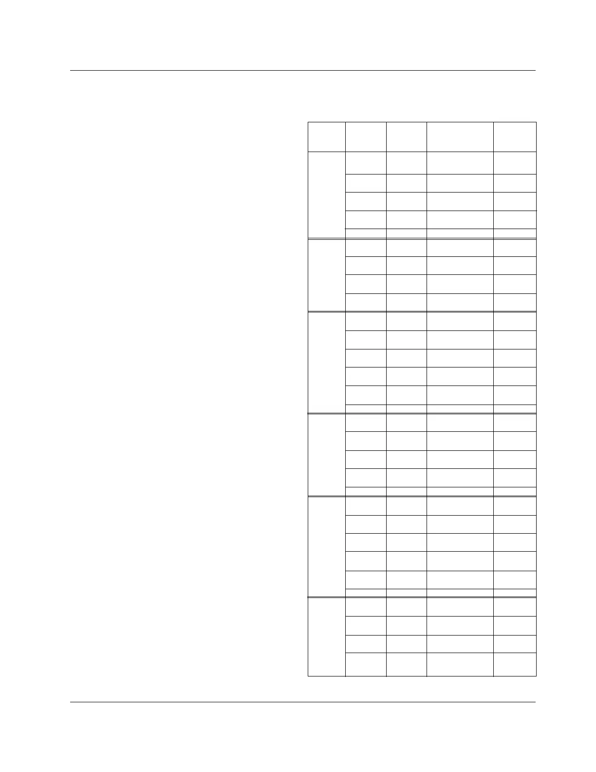
Table 3-1
Tap Changer Model Application Chart.
Note: An "S" following the kVA denotes station mount.
Spring-drive: 928D and 170C
Direct-drive: 770B and 660C
Rated Load
Volts Current Rated Tap
(kV) (Amp) kVA Catalog Number Changer
2.5 100 25 RSAA025025AA 928D
200 50 RSAA025050AA 928D
60 300 75 RSAA025075AA 770B
kV 400 100 RSAA025100AA 770B
500 125 RSAA025125AA 660C
668 167 RSAA025167AA 660C
1000 250 S RSAA025250AA 770B
1332 333 S RSAA025333AA 770B
1665 416.3 S RSAA025416AA 770B
5.0 50 25 RSAA050025AA 928D
100 50 RSAA050050AA 928D
75 200 100 RSAA050100AA 928D
kV 250 125 RSAA050125AA 770B
BIL 334 167 RSAA050167AA 770B
500 250 S RSAA050250AA 660C
668 333 S RSAA050333AA 660C
833 416.3 S RSAA050416AA 660C
7.62 50 38.1 RSAA076038AA 928D
75 57.2 RSAA076057AA 928D
95 100 76.2 RSAA076076AA 928D
kV 150 114.3 RSAA076114AA 928D
BIL 219 167 RSAA076167AA 928D
328 250 S RSAA076250AA 770B
438 333 S RSAA076333AA 660C
548 416.3 S RSAA076416AA 660C
656 500 S RSAA076500AA 660C
875 667 S RSAA076667AA 660C
1093 833 S RSAA076833AA 660C
13.8 50 69 RSAA138069AA 170C
100 138 RSAA138138AA 170C
150 207 RSAA138207AA 170C
95 200 276 S RSAA138276AA 170C
BIVL 300 414 S RSAA138414AA 770B
362 500 S RSAA138500AA 660C
400 552 S RSAA138552AA 660C
483 667 S RSAA138667AA 660C
604 833 S RSAA138833AA 660C
14.4 5 72 RSAA144072AA 170C
100 144 RSAA144144AA 170C
200 288 S RSAA144288AA 170C
231 333 S RSM144333AA 770B
150 289 416 S RSAA144416AA 770B
BklVL 300 432 S RSM144432AA 770B
347 500 S RSAA144500AA 660C
400 576 S RSAA144576M 660C
463 667 S RSAA144667AA 660C
500 720 S RSAA144720AA 660C
578 833 S RSAA144833AA 660C
19.92 25.1 50 RSM199050AA 170C
50.2 100 RSAA199100AA 170C
100.4 200 S RSAA199200AA 170C
1k5v0 167 333 S RSM199333AA 770B
BIL 200.8 400 S RSAA199400AA 770B
250 500 S RSAA199500AA 770B
335 667 S RSAA199667AA 660C
418 833 S RSAA199833AA 660C