1-8
VR-32 Regulator and CL-2A Control
3. Raise the cover assembly and attached components over
the tank. Make certain of proper orientation.
4. Lower the unit, positioning the channels in the tank guides.
Guide the control cabinet onto its brackets.
5. Seat the unit in the tank. Tighten the cover clamps or bolts
and replace the control mounting bolts.
NOTE: Tap the cover with a rubber hammer around the
edge to properly seal the gasket while tightening the cover
band.
6. Check and retighten horizontal side channel bolts through
handhole, if required.
Maintenance
The following is the recommended maintenance program for a
regulator that has been untanked:
1. Check all connections for tightness.
2. Check all contacts for wear (refer to
S225-10-2).
3. Avoid removing the main core-and-coil assembly from the
oil, except when a winding failure occurs. Blocking between
the cover and tank lip should be employed to suspend the
core-and-coil assembly within the oil until inspection of the
tap changer or other maintenance is complete.
WARNING: When the internal assembly is lifted
for inspection or maintenance, blocking should be
placed between the cover and the top of the tank to
keep the assembly from falling should lifting apparatus
fail.
!
If it is necessary to remove the main core-and-coil assembly
from the oil, the following steps should be followed.
A. The tap changer must not be subjected to temperatures
above 66
o
C. (150
o
F). It must be removed if the unit is
baked at higher temperatures.
B. If the unit is out of oil more than four hours, it must be
rebaked for a minimum of 24 hours at 100
o
C (212
o
F).
The maximum number of times a unit should be rebaked
is twice.
C. Within four hours after bake, the unit should be retanked
and filled with oil.
D. It is recommended that a vacuum be pulled on the unit
for at least one hour (2 mm. of vacuum or better) after the
unit is completely refilled with oil. If vacuum processing is
not available, allow the entire internal assembly to soak
in the oil for at least five days before energizing.
E. Do not test the unit until either the vacuum processing or
the soaking has been completed.
4. Consider upgrading controls to latest design.
CO N ST R U CTIO N
Surge Protection
SERIES SURGE ARRESTER
All VR-32 regulators are equipped with a bypass arrester con-
nected across the series winding between the source (S) and
load (L) bushings. This bypass arrester limits the voltage devel-
oped across the series winding during lightning strikes, switch-
ing surges, and line faults. The series surge arrester can be
seen in Figure 1-2. A MoV-type series surge arrester of 2.2 kV
offers series winding protection on all regulators except those
rated over 14,400 volts which have a 3/4.5-kV MoV-type series
surge arrester.
SHUNT ARRESTERS
A shunt arrester is an optional accessory on the VR-32 regula-
tor for protection of the shunt winding. The shunt arrester is a
direct connected arrester mounted on the tank and connected between
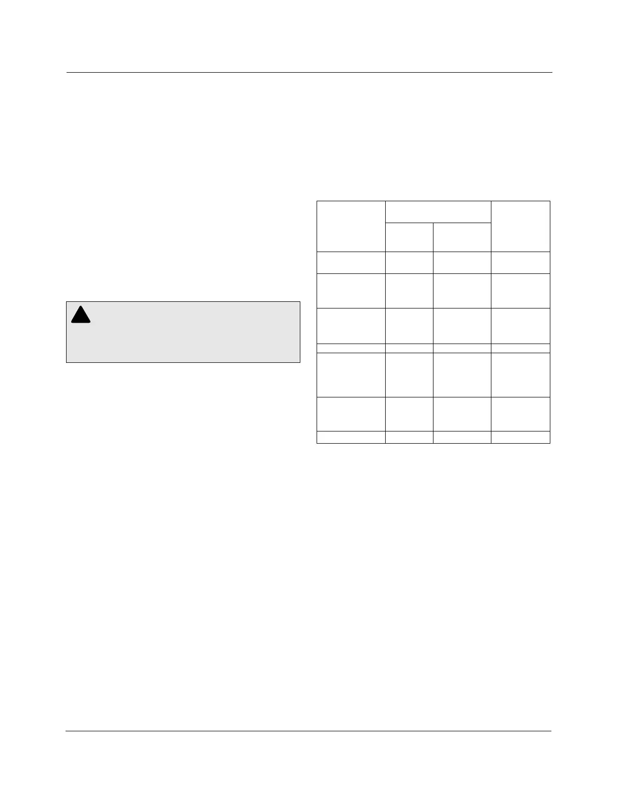
TABLE 1-1
Shunt Arrester Application Data.
the “L” bushing and ground. For additional protection a shunt
arrester may also be installed between the S (source) bushing
and ground.
For best results, locate these arresters on the mounting pads
provided on the tank near the bushing. Ground the arrester and
the regulator tank to the same ground connection using the
shortest cable possible. Shunt arrester application data is listed
in Table 1-1.
Nominal System Voltages Recommended
(volts) MOV
Regulator Shunt
Voltage Delta or Multi-Grounded Arrester
Rating Single-Phase Wye Ratings
(kV)
2500/4330Y 2400 2400/4160
2500 2500/4330 3
4160 4160/7200
5000/8660Y 4330 4330/7500
4800 4800/8320 6
5000 5000/8660
6900 6900/11950
7620/13200Y 7200 7200/12470 9
7620 7620/13200
7970
7970/13800 10
12000
12470
13800 13200 15
13800
14400
13800/23900
14400/24940Y 14400/24940 18
19920/34500GrdY 19920/34500 27
Position Indicator & ADD-AMP Capability
The position indicator (Figure 1-8) is mounted on a junction box
on the cover of the regulator and is directly connected to the tap
changer by a flexible drive shaft passing through the junction
box and terminal board via a sealing gland.
The indicator face is graduated in steps, numbered 1 through
16, on each side of zero, which designates neutral. Drag hands
indicate the maximum and minimum positions attained during
raise and lower operations. The drag hands are automatically
reset around the position indicator hand by operating the drag
hand reset switch on the control front panel.
The ADD-AMP feature of VR-32 regulators allows increased
current capacity by reducing the regulation range. This is
accomplished by setting limit switches in the position indicator
to prevent the tap changer from traveling beyond a set position
in either raise or lower directions. The limit switches have
scales graduated in % regulation, and are adjustable to specific
values of 5, 6-1/4, 7-1/2, 8-3/4, and 10% regulation to alter the
regulation range. The five possible load current ratings associ-
ated with the reduced regulation ranges are summarized in
Table 1-2. At each setting a detent stop provides positive
adjustment. Settings other than those with stops are not recom-
mended. The raise and lower limits need not be the same
value.