S225-10-5
1-9
Setting The Limit Switches
Before setting the limit switches, be sure the new settings
will not conflict with the present tap changer position. Do not
set the switches below the indicated tap changer position.
For example, if the indicator hand is at step 12 and the
change to be made is from plus or minus 10% (step 16) to
plus or minus 5% (step 8), run the tap changer back to step
7 or less, manually. Then set the limit switches for plus or
minus 5% regulation.
Limit switches should be set in anticipation of the maxi-
mum deviation of primary voltage. For example, on a circuit
where 7200 volts is to be maintained, plus or minus 10% will
permit voltages between 6480 and 7920 to be regulated
effectively. For voltages outside of this range, the regulator
will not be able to return the voltage to the preselected level,
in this case 7200 volts. The tap changer will have stepped to
the maximum tap position and will be unable to regulate fur-
ther. Five % regulation would accommodate circuit voltages
between 6840 and 7560, maintaining 7200 volts for all volt-
ages in this range.
To set the limit switches. follow this two-step procedure:
1. Loosen the captive bezel securing screws and swing the
bezel open.
2. Lift the limit switch adjustment lever free of the detent and
slide it to the new setting allowing the lever to snap into
the detent stop.
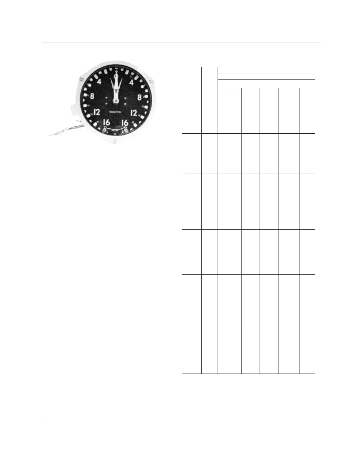
Figure 1-8.
Position Indicator.
TABLE 1-2
ADD-AMP Capabilities.
**55/65
o
C rise rating on VR-32 regulators gives an additional 12%
increase in capacity if the tap changer’s maximum current rating has
not been exceeded. For loading in excess of the above values please
refer to the factory.
Load Current Ratings (amps)
Rated Rated Regulation Range
Volts kVA
± 10%** ± 8-3/4% ± 7% ± 6-1/4% ± 5%
25 100/112 110 120 135 160
50 200/224 220 240 270 320
75 300/336 330 360 405 480
100 400/448 440 480 540 640
2500 125 500/560 550 600 668 668
167 668 668 668 668 668
250 1000/1120 1000 1000 1000 1000
333 1332/1492 1332 1332 1332 1332
416.3 1665/1865 1665 1665 1665 1665
25 50/56 55 60 68 80
50 100/112 110 120 135 160
100 200/224 220 240 270 320
125 250/280 275 300 338 400
5000 167 334/374 367 401 451 534
250 500/560 550 600 668 668
333 668 668 668 668 668
416.3 833/900 833 833 833 833
38.1 50/56 55 60 68 80
57.2 75/84 83 90 101 120
76.2 100/112 110 120 135 160
114.3 150/168 165 180 203 240
167 219/245 241 263 296 350
7620 250 328/367 361 394 443 525
333 438/491 482 526 591 668
416.3 548/614 603 658 668 668
500 656/668 668 668 668 668
667 875/900 875 875 875 875
833 1093/1224 1093 1093 1093 1093
69 50/56 55 60 68 80
138 100/112 110 120 135 16
207 150/168 165 180 203 24
276 200/224 220 240 270 32
13800 414 300/336 330 360 405 48
500 362/405 398 434 489 579
552 400/448 440 480 540 64
667 483/541 531 580 652 668
833 604/668 664 668 668 668
72 50/56 55 60 68 80
144 100/112 110 120 135 16
288 200/224 220 240 270 320
333 231/259 254 277 312 37
416 289/324 318 347 390 462
14400 432 300/336 330 360 405 480
500 347/389 382 416 468 555
576 400/448 440 480 540 64
667 463/519 509 556 625 668
720 500/560 550 600 668 668
833 578/647 636 668 668 668
50 25.1/28 28 30 34 40
100 50.2/56 55 60 68 80
200 100.4/112 110 120 135 16
19920 333 167/187 184 200 225 267
400 200.8/224 220 240 270 32
500 250/280 275 300 338 400
667 335/375 369 402 452 536
833 418/468 460 502 564 668