1-4
Figure 1-3.
Nameplate.
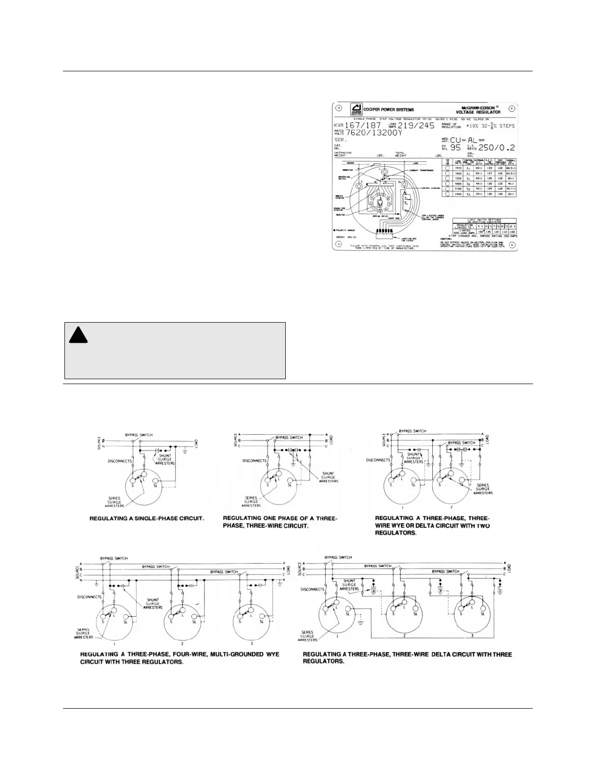
Figure 1-4.
Typical connections diagrams.
VR-32 Regulator and CL-2A Control
WARNING: Connect the "S" bushing to the
SOURCE, the "L" bushing to the LOAD, and the
"SL" bushing to NEUTRAL. To do otherwise may cause
excessively high or low voltage on the load side of the
regulator or cause severe damage to the regulator.
!
Nameplate
The VR-32 nameplate (Figure 1-3) prominently displays the
55/65°C temperature rise rating of the regulator. The sealed-
tank system along with the 65°C rise winding insulation allows
the regulator to be used at this dual rating. This provides an
additional 12 percent capacity without loss of normal insulation
life.
The nameplate is stamped with pertinent rating information
and includes the schematic diagram of the VR-32 internal
design. Refer to the nameplate to determine the correct adjust-
ment for the required regulated load voltage. A movable peg on
the nameplate indicates the tap and load voltage in use.
Systems Connections
A regulator can regulate a single-phase circuit, or one phase of
a three-phase wye or delta circuit. Two regulators connected
phase-to-phase in open-delta, or three regulators connected
phase-to-phase in closed-delta, can regulate a three-phase,
three-wire delta circuit. When connected in wye, three regula-
tors can regulate a three-phase, four-wire multi-grounded wye
circuit. Three regulators cannot be connected in wye on three-
phase, three-wire circuits because of the probability of neutral
shift. Typical connection diagrams are illustrated in Figure 1-4.