7-1
APPENDIX • Section 7
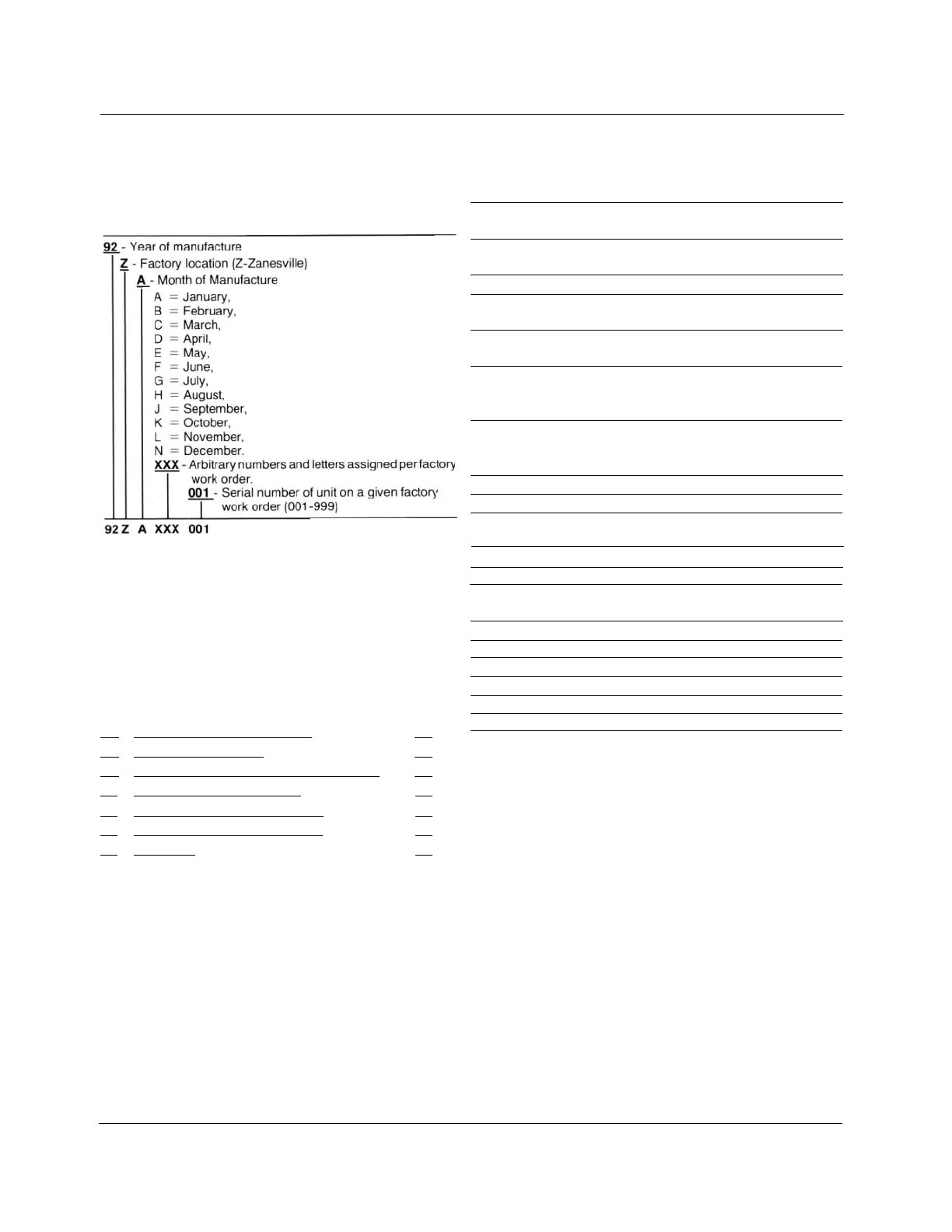
SERIAL NUMBERS
Serial numbers for Cooper
Power System's regulators are coded in the following manner:
LIST OF TABLES
The following is a list of all tables found in this document and
the page on which they are located.
LIST OF SCHEMATIC DIAGRAMS
Table Page
Number Table Title Number
1-1
Shunt Arrester Application Data. 1-8
1-2 ADD-AMP Capabilities. 1-9
2-1 VR-32 Tap Connections and Voltage Levels. 2-7
2-2 Current Transformer Applications. 2-9
3-1 Tap Changer Model Application Chart. 3-1
4-1 Power Supply Voltages at Test Points. 4-9
6-1 Spare parts. 6-1
Figure Description Page
1-4 Typical Connection Diagrams 1-4
1-9 Power Circuit - Series Winding Located on the
Source Side 1-13
1-10 Power Circuit - Series Winding Located on the
Load Side 1-11
1-11 Power Circuit - Series Transformer 1-11
1-13 Internal Wiring of Spring-Drive Regulator with
Series Winding Located on the Source Side 1-12
1-14 Internal Wiring of Direct-Drive Regulator with
Series Winding Located on the Load Side 1-13
1-15 Internal Wiring of Regulator with Series Wind-
ing on the Input Side, with Differential Potential
Transformer 1-14
1-16 Internal Wiring of Regulator with Load Winding
on the output Side, with Differential Potential
Transformer 1-15
1-17 Back Panel Signal Circuit 1-16
2-2 Dipswitch Location on Printed Circuit Board 2-3
2-3 VR-32 Regulator and CL-2A Control Wiring
Schematic Diagram 2-5
2-7 SCADA Connections to CL-2A Control 2-11
2-8 SCADA Connections Basic Scheme 2-12
2-9 Typical User Provided Voltage Reduction
Module 2-12
2-10 8 - Conductor Cable 2-13
2-11 9 - Conductor Cable 2-13
2-12 10 - Conductor Cable 2-13
4-1 Junction Box Wiring Diagram 4-1
4-2 Physical Wiring 4-5
4-3 Printed Circuit Board Schematic 4-7
S225-10-5