VR-32 Regulator and CL-2A Control
2-11
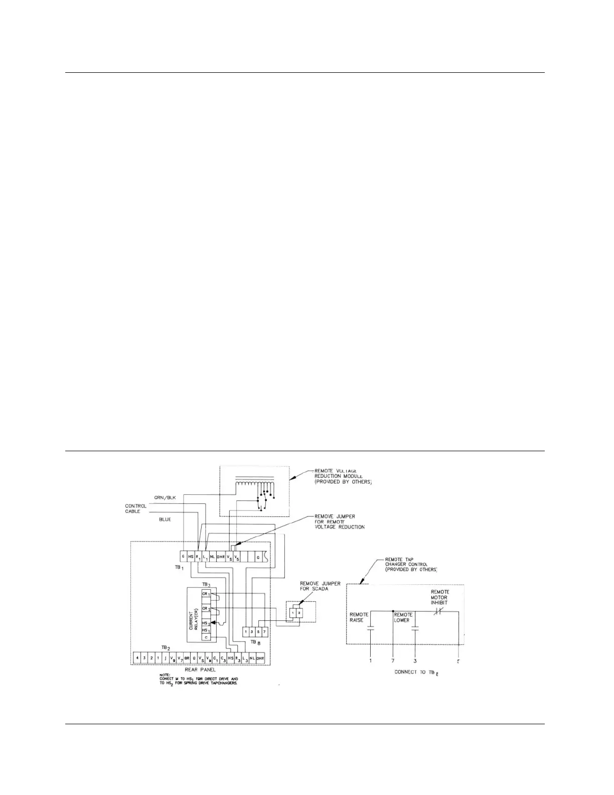
Figure 2-7.
SCADA connections to CL-2A control.
This section applies to regulator SCADA applications that
have seen increased use on distribution systems. Cooper
Power Systems has prepared a connection scheme to accom-
modate various functions while at the same time protecting the
equipment. This scheme accommodates the following func-
tions:
1. Remotely raise and lower the tap changer
2. Remotely block automatic operation
3. Remotely apply voltage reduction
The basic requirement of the scheme is the use of the cur-
rent relay package. The purpose of the current relay package
is to prevent misapplication of any SCADA system, and to
work with the holding switch to make sure a tap change is
completed once it is started. The scheme uses a current relay
to sense when the holding switch is closed. Once the holding
switch is closed, the current relay contacts open and prevent
any further power from being applied to the motor except
through the holding switch. When the holding switch opens,
the current relay contacts close, returning control of the tap
changer to one of the operational methods of control: AUTO,
MANUAL, or SCADA.
Figure 2-7 shows the basic scheme and the function of the
current relay. This general scheme applies to all Cooper
Power Systems CL regulator controls, but the wiring changes
necessary to achieve the scheme differ with the different con-
trols. The blocking (motor inhibiting) contact, shown in Figure
2-8 inhibits automatic operation of the regulator when the
SCADA scheme is in operation.
VOLTAGE REDUCTION
The use of voltage reduction is common with SCADA
schemes. Figure 2-9, shows a typical voltage reduction
method. The input voltage to the control is applied between
V(in) and common. The output voltage V(out) to common is
applied to the sensing circuit. If relay K is energized, V(out) is
greater than V(in) and when this increased voltage is applied,
he sensing circuit causes the control to lower the voltage by the
amount of increase. Various levels of voltage reduction may be
selected, depending upon the number and value of each tap on
the auto-transformer. The total range is usually 0 to 10%.
NOTE: This discussion assumes that the Cooper Power Systems
voltage reduction accessory is not being used, and SCADA
equipment is being connected directly to the bare CL-2A Control.
Refer to Figure 2-9 for proper connections. This method of volt-
age reduction is not recommended if a metering device such as
the Cooper Power System's Meter-Pac is used.
RETROFITTING A CL-2A CONTROL TO
PREVIOUS REGULATOR DESIGNS
Most Cooper Power Systems VR-32 voltage regulators produced
since 1957 can be upgraded to work with the CL-2A control. This
does not include simplified regulators (SR-32 or Auto-Boosters
®
).
This does include the line material control (1957-1963) in the
RS13Y series, the Kyle control (1963-69) in the RS83Y series,
the Canonsburg control (1969-77) in the TAB142045 or B843449
series and the CL-1 control (1977-82).
Earlier pole-star types, built in Canonsburg, cannot be
retrofitted using these instructions. The following applies to pre-
CL-1 design regulators:
A complete CL-2A control (part code #6070) must be retrofit to
the older regulator. This includes the cabinet, back panel and
front panel. The original control cable should be reused where
possible to simplify rewiring. If this is impossible, the factory
should be contacted for additional instructions. Note that all con-
trol accessories can be utilized with the retrofit CL-2A, providing
increased versatility of the regulator.