S225-10-5
2-12
Figure 2-8.
SCADA connections to basic scheme.
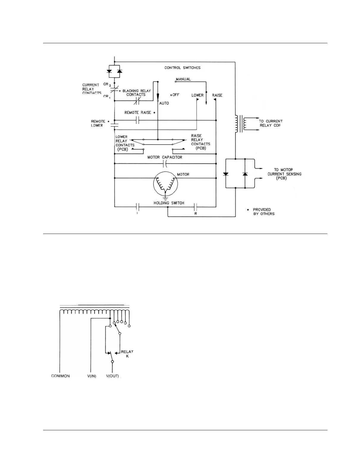
Figure 2-9.
Typical user provided voltage reduction module.
1. Count the number of wires in the existing control cable to
determine which wiring schematic applies to your regulator.
All VR-32 regulators produced in this period had either 8, 9,
or 10 conductors in the control cable (Figure 2-10, 2-11, or 2-
12).
2. Determine if the regulator is to be used at rated voltage, or at
a lower tapped voltage. This can be found by referring to
Table 2-1 on page 2-7. Using the regulator voltage rating,
found on the nameplate, find the voltage rating in column 1 of
Table 2-1. Then determine the nominal single-phase voltage
at which the regulator will be used. Typical system voltages
are found in column 2. If the exact system voltage is not list-
ed, find the closest one. Then determine what internal tap is
listed in column 3 for that system voltage.
A. If it is “E1/P1” then the standard, current design CL2A
control will work. order standard part code #6070 and
install as indicated.
B. If it is either “E2/P2 or E3/P3” then a modified CL-2A must
be used. This modification includes a special ratio cor-
rection transformer on the back panel. Call factory for
order information.
3. Note that the tap changer terminal board (TCB) wiring is
shown, but no modifications are required here. The discon-
nect plug in the existing control cable will still be operative.
The 10 conductor cable schematic required that one voltage
lead the white/black wire from V
2
, be cut and insulated. It
could also be disconnected at V
2
terminal on TCB located on
the tap changer.
4. Tighten the waterproof lock-nut on cabinet top to the cable
and cabinet.
5. Perform the operational check as described on page 2-2 to
ensure correct operation.