6-1
SPARE PARTS • Section 6
When ordering replacement parts or field-installable acces-
sories for your Cooper Power Systems VR-32 step-voltage reg-
ulator, provide the following information:
1. Regulator serial number (found on control nameplate).
2. Quantity of each part required.
3. Part code number of each part (as shown in Table 6-1).
4. Description of each part (as shown in Table 6-1).
Additional parts and installation information for tap changers is
found in bulletin
S225-10-2.
*Motor Kits include motor, capacitor and hardware.
**When contact viewed from motor-side of tap changer.
***Current design has 10 conductors. 12 conductor cables with required terminations are available for obsolete designs or to mount CL-4C on previous designs. Contact
factory service department for details.
+ See parts manual or contact factory service department.
• other lengths available. Contact factory service department.
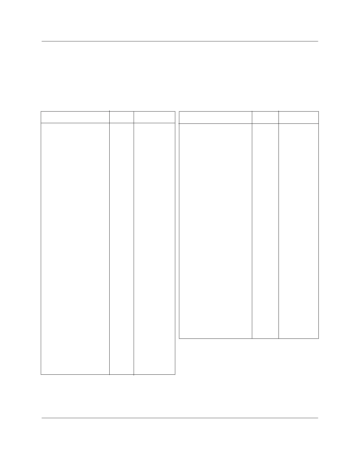
Table 6-1
Spare Parts
Part
Description Code No. Reterence Figure
• 66OC Direct-drive tap changer parts
Replacement motor kit A. 3031 Figure 6-4
Main movable contact 3029 Figure 6-4
Main stationary contact 3023 Figure 6-4
Reversing stationary contact 3037 Figure 6-4
Reversing stationary neutral 3027 Figure 6-4
contact (non-arcing)
Reversing movable contact 3036 Figure 6-4
• CL control parts
Complete CL-2A control 6070 (not shown)
(includes 6500, back panel,
cabinet, no cable)
CL-2A front panel only 6030 Figure 2-1
(includes all operational
electronics of control)
CL-2A printed Circuit board 6063
Neutral light bulb 6051 Figure 2-1
Motor fuse (6A) (pack of 5) 6047 Figure 2-1
Panel fuse (2A) (pack of 5) 6048 Figure 2-1
CR relay and terminal strip 6071 Figure 5-2
• Control cable***
15’ for remote mounting 6104 (not shown)
20’ for remote mounting 6105 (not shown)
25’ for remote mounting 6106 (not shown)
30’ for remote mounting 6107 (not shown)
•
• Field-installable accessories
See page 5-1 for further
information.
Control cabinet heater 9000 Figure 5-1
Fan cooling 9005 Figure 5-5
Auxiliary control cabinet and 9050 (not shown)
hardware
Voltage Reduction Control 9040 Figure 5-2
Voltage Limiter 9065 Figure 5-3
Meter Pac 9075 Figure 5-5
Auxiliary Current Transformer 9055 Figure 5-4
• Accessories for data extraction.
Data Reader & Software Kit 9076 Figure 5-2
Data Reader Assembly 9977 (not shown)
Part
Description Code No Reference Figure
• Bypass series arrester 5004 Figure 1-2
(with mounting hardware)
• Complete bushing assembly
(indicate if for S, L, or SL
application)
Dry-type (95 kV BIL and below) + Figure 6-1
Oil-filled (150 kV BIL and above) + (not shown)
(Note oil-filled bushings available
only as complete assembly )
• Dry-type bushing components
Terminal cap + Figure 6-1
Terminal cap gasket + Figure 6-1
Porcelain + Figure 6-1
Bushing/tank gasket + Figure 6-1
Clamp w/bolts + Figure 6-1
Clamp spring + Figure 6-1
• Position indicator (complete) 4000 Figure 1-8
• Position indicator glass cover 4001 Figure 1-8
• Position indicator external 4004 (not shown)
drive cable (not used on regulators
without junction box)
• Position indicator internal drive + (not shown)
cable (provide total length of old
cable in inches)
• 928D and 170C Spring-drive
tap changer parts
Replacement motor kit A 3014 Figure 6-2
(with sprocket and pin)
Main movable contact right hand* 3007 Figure 6-2
Main movable contact left hand** 3006 Figure 6-2
Main stationary contact 3002 Figure 6-2
Reversing stationary contact 3004 Figure 6-2
right hand**
Reversing stationary contact
left hand** 3003 Figure 6-2
Reversing movable 3022 Figure 6-2
contact—928D
Reversing movable 3005 Figure 6-2
contact—170C
• 770B Direct-drive tap changer parts
Replacement motor kit A. 3031 Figure 6-4
(use old shield)
Replacement motor shield 3068 Figure 6-3
Main or reversing 3059 Figure 6-3
movable contact
Main stationary contact 30s3 Figure 6-3
Reversing stationary contact 3067 Figure 6-3
Reversing stationary neutral 3057 Figure 6-3
contact (non-arcing)
VR-32 Regulator and CL-2A Control