Condition Probable Fault
TP
1
Low D
5
, D
6
, D
7
, D
8
TP
2
Off R
g
, IC
3
, C
4
or lC
1
TP
3
Off IC
8
, D
1
, IC
5
or lC
1
TP
4
Off R6, Z
2
, C
11
or IC
4
TP
3
and TP
4
Low D
2
, D
3
, C
18
, lC
8
VR-32 Regulator and CL-2A Control
4-9
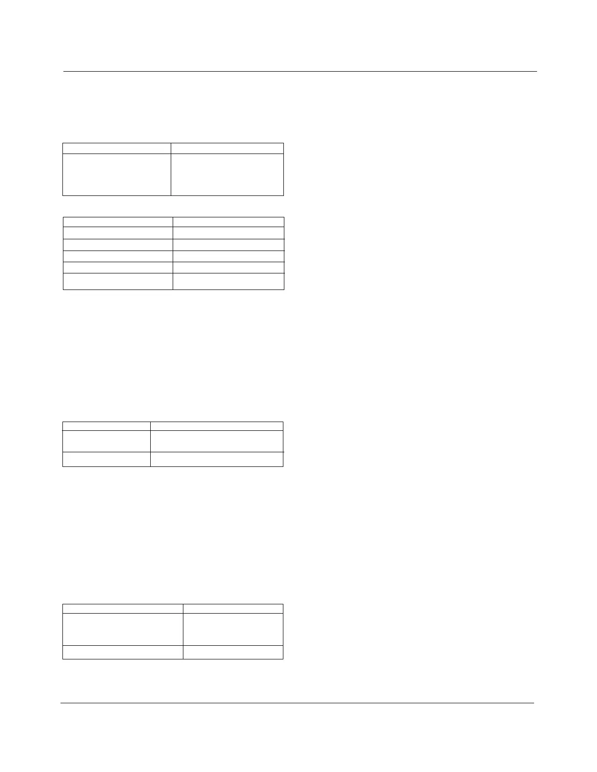
Now, with the input voltage set at nominal (in band), the fol-
lowing power supply voltages should be obtained between the
specified test point and TP
0
:
Table 4-1
Power Supply Voltages at Test Points
Failure to Conform #1
Failure to Conform #2
Failure to Conform #3
Test Point Volts dc
TP
1
+28 ± 15%
TP
2
+5.0 ± 2%
TP
3
+5.0 ± 5%
TP
4
+7.0 ± 10%
If all power supply voltages are correct, each circuit generating
an input to the microcomputer should be checked by taking
the following steps:
CHECK NO. 2 - INPUT AND FILTERING
1. Connect the multimeter to test points TP
0
and TP
5
.
2. Measure 2.5 volts dc ± 5% at TP
5
.
3. Connect an ac coupled meter having a 200 millivolt range to
test points TP
0
and TP
5
. The reading should be less than
100 millivolts.
Condition Probable Fault
DC Voltage Off Any components up to TPs in
the input section
AC Ripple High D
9
, D
10
, D
11
, D
12
, C
22
, C
3
CHECK NO. 3 - DIFFERENTIAL AMPLIFIER
1. Connect the multimeter to test points TP
0
to TP
6
.
2. Adjust the input supply until the reading at TP
6
is 2.5 volts
dc. The input should be 60 volts ac or 120 volts ac ±5%,
depending upon the board being out of or in the control,
respectively.
3. Switch the multimeter to ac and read less than 20 millivolts.
4. Switch back to dc.
5. Vary the input and read a 0.625-volt change at TP
6
for
each 2.0-volts ac change in the input related to the 120
volts ac input supply.
Condition Probable Fault
Input supply out of tolerance for R
17
, R
18
, C
6
, or IC
4
2.5 volts ac at TP
6
or ac ripple
high
Output swing to input swing Off R
19
, R
17
, R
18
, R
20
or IC
4
CHECK NO. 4 - MOTOR CURRENT SENSE
To test the motor current sensing circuitry of the circuit board,
approximately .120 amps of current must be applied to the
CURRENT SENSE input (terminals 1 & 2). This is accomplished
as follows:
1. First connect the multimeter from TP
0
to TP
7
, set for DC volts of
a scale to read up to 5.0 volts.
2. With the board in the control, connect a 1000-ohm, 20-watt resis-
tor momentarily from G to HS, on the fanning strip which leads
to the back panel. The control should be powered externally with
a 120 volt supply, attached to the EXTERNAL SOURCE termi-
nals.
3. With the board out of the control, the same resistance can be
used in series with a 120-volt ac supply, applied to the motor cur-
rent sense terminals of the circuit board.
4. For either case, with the current applied, at least 1.5 volts should
be measured. With the current removed, less than 0.4 volts
should be measured. Failure to conform can involve any compo-
nent in the motor current sense circuit.
CHECK NO. 5 - BANDWIDTH AND TIME DELAY CONTROLS
If no fault is found in any of the previous circuits, the bandwidth and
time delay switches can be checked. As viewed from the back
(component side), 13 terminals are readily visible on each switch.
The terminal located at 11 o’clock is the center pole of the switch
and is connected directly to ground.
1. Connect the multimeter to TP
0
, set for DC volts of a scale to
read up to 5.0 volts.
2. Each terminal on the switch should measure at least 3.0 volts,
except the center pole and the terminal which corresponds to
the present switch setting, which will read zero (0). As each
switch is rotated through its settings, the “grounded” terminal
should move accordingly. Note, on the bandwidth switch, that
only 11 positions are actively used and that position 12 is con-
nected together with position 11.
3. Failure to conform indicates a defective switch, or resistor pack-
ages RP
1
, RP
2
, RP
3
, RP
4
, or decoders IC
2
and IC
6
.
CHECK NO. 6 - BAND EDGE LIGHT CIRCUITS
If the symptoms of the malfunction indicate the problem may be in
the HIGH or LOW band edge lights, they may be checked as
follows:
1. Set the control for 120.0 V setting and a 2 V bandwidth.
2. Apply 120.0 V ac to the EXTERNAL SOURCE terminals, place
the power switch on EXTERNAL, and the AUTO/OFF/ MANUAL
switch on AUTO.
3. Connect the multimeter toTP
0
, set for dc volts of a scale to read
up to 28 volts. Connect the positive meter lead to TP
14
, and
expect to measure approximately 28 V.
4. Now, slowly vary the applied voltage to below 119 V, and
observe the LOW BAND indicator, expecting it to light. The volt-
age at TP
14
should correspondingly drop to less than 1 V.
5. If the indicator does not light, but TP
14
does go low, the problem
is a defective LED DS
1
, or resistor R
23
. If TP
14
does not go low,
then the problem may be a defective IC
7
.
6. Now, reconnect the multimeter to TP
15
and expect to measure
approximately 28 V.
7. Vary the applied voltage to above 121 V, and observe the HIGH
BAND indicator, expecting it to light. The voltage at TP
15
should
correspondingly drop to less than 1 V.
8. If the indicator does not light, but TP1s does go low, the problem
is a defective LED DS
2
, or resistor R
22
. If TP
15
does not go low,
then the problem may be a defective IC
7
.