Additional Wiring Detail
ote: N Wiring terminal may face alternate direction.
Connections should be made to terminal blocks on
the side that is not pre-wired by the factory. Observe
color and labeling which designates Hot and Neutral
location for each terminal.
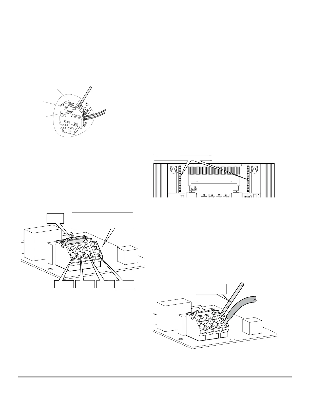
Load Wiring
High Voltage Load Wiring
Each load channel is served by a dedicated control card
fed from a designated circuit breaker. For each card, load
connections are made using a four-way rapid connection
block.
Available at the connection block are a permanent Hot
(subject to circuit breaker status), Switched hot (via relay
control), Dimmed hot (via triac control) and Neutral - see
diagram below.
ote: N Earth connections for each channel are made using
the connector blocks located at the top of each
wireway (see the figure for Earth Connection).
A red 3-way bypass jumper is installed within each
connection block to serve three purposes:
• To bind the three outputs in order to protect each channel
card from load faults during installation
• To energize each channel output (subject to the status of
the associated circuit breaker) for use as work
lighting control during installation and
• To assist with circuit testing during commissioning
IMPORTANT: The bypass jumper must remain in place on
each channel until the commissioning process is complete.
Total Load Per Channel
The load on each channel must not exceed 16A.
Load Wire Gauges
Load wiring must be sized according to the nature of
the channel load(s) and with strict regard to regulations
and codes in force within your locality. The maximum
permissible wire gauges accepted by the connector blocks
are:
Solid wire: 10 AWG (6 mm
2
)
Stranded wire: 12 AWG (4 mm
2
)
Earth Connections
Earth connections for each channel are available at the
connector blocks located at the top of each wireway:
To Insert a Wire
1. Strip roughly a quarter inch (6 mm) of insulation from
the wire end.
2. Place a small flat blade screwdriver all the way into the
upper rectangular hole (keep the tip of the screwdriver
against the top edge of the hole).
3. Press the screwdriver tip downwards towards the base
of the connection block and push the stripped wire into
the large circular hole.
4. When the wire is in place, release the screwdriver and
check that the wire is firmly held by the internal spring
clip.
Dimmed
Hot
Neutral
Switched
Hot
Hot (Live)
Bypass
Jumper
(Orange)
Disconnect Lever
Hot (Blue
Terminal)
Neutral (White
Terminal)
As Per Each
Channel
Maximum Wire Gauges
Solid Wire: 10 AWG (6 mm
2
)
Stranded Wire: 12 AWG (4 mm
2
)
Load Earth Connector Blocks
Small Flatblade
Screwdriver
0.14 tp 6mm2 Max
26 to 10 Awg Max
Universal Source Controller - Feed ThruWaveLinx Wired
9850-000234-02 page 10
May 2024
www.cooperlighting.com