Low Voltage Load Wiring
Each channel can be individually configured to support any
of the following low voltage load control standards: 0-10V,
DSI or broadcast DALI (DSI and DALI - Canada and Mexico
Only). The high voltage sections for each channel continue
to provide switched hot outputs to power the controlled
loads.
ote: N Support for multiple low voltage load control
standards may not be permissible in certain
countries. In such cases, the required control
standard must be stated when ordering.
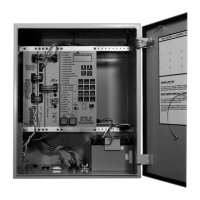
The low voltage load wiring circuits are located just below
the control panel, accessible either through a removable
mini panel or when the complete casing is removed.
Connections are made easy by using removable plug blocks
which snap into terminals mounted on the circuit boards
shown below:
signal
signal
signal
signal
13 19
14 20
15 21
0
16 22
1
17 23
2
18 24
0V
0V
0V
0V
signal
signal
signal
signal
0V
0V
0V
0V
signal
signal
signal
signal
0V
0V
0V
0V
signal
signal
signal
signal
0V
0V
0V
0V
signal
signal
signal
signal
0V
0V
0V
0V
signal
signal
signal
signal
0V
0V
0V
0V
For each circuit, the low voltage control protocol to be used
is selected using the configuration menu on the control
panel. The programming of the Source Controller channels
is covered within the accompanying System Manual.
ote: N DALI signals for each channel are output in broadcast
mode only - it is not possible to individually address
multiple DALI luminaires on the same control wire.
The low voltage load control circuits are PELV (Protected
Extra Low Voltage).
Low Voltage Load Wiring Flows
The casing provides four knockouts on the base panel for
use by exiting low voltage load cables as well as control
wiring. Each knockout is 0.89 inches (22.5 mm) in diameter.
Use appropriate conduits and couplers to link with raceways
or cable runs, as necessary.
IMPORTANT: Low voltage load wiring should be installed
with a suitable separation to parallel high voltage cables,
according to local and national codes.
Indicators
An indicator is assigned to each low voltage output channel
to provide quick visual feedback. In each case, the indicator
(located next to the output connectors) will mimic the
dimmed status of the associated channel, from zero to full
brightness.
Indicators
Universal Source Controller - Feed ThruWaveLinx Wired
9850-000234-02 page 12
May 2024
www.cooperlighting.com