High Voltage Load Wiring Flows
A knockout (diameter 2.42 inches/61.5 mm) is provided
above each load wireway within the top panel of the chassis.
Use suitable conduits and couplers. Please see the wiring
flow diagram on page 8.
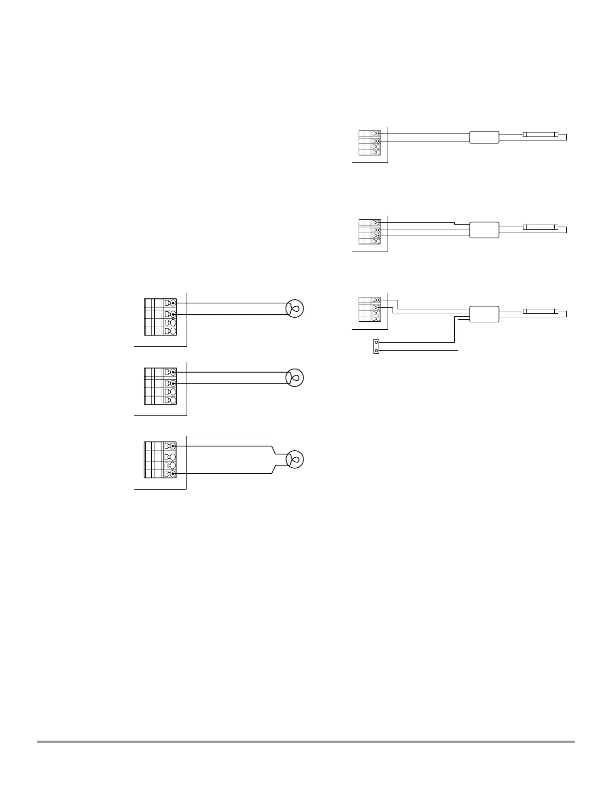
Typical Load Connections
The examples below show some of the most typical loads
and the way in which they are connected to a Source
Controller dimmer card.
Dening Load Types
The type of load placed upon each channel must be
defined within the Configuration menu of the control panel.
For further details on how to do this, please refer to the
accompanying System manual.
Standard Dimmable Load
Non-Dim Load
Constant Load
2 Wire Fluorescent Dimmable Ballast
(E.g. Advance Mark X™)
3 Wire Fluorescent Dimmable Ballast
(E.g. Lutron
®
Hi-Lume
®
Or Eco-10™)
4 Wire Fluorescent Dimmable Ballast
(E.g. 0-10 VDC Control)
[Neutral - White]
[Neutral - White]
[Neutral - White]
[Neutral - White]
[Neutral - White]
[Neutral - White]
Ballast
Lutron
®
Ballast
0-10V
Ballast
Lamp
Lamp
Lamp
[Dimmed Hot - Black]
[Dimmed Hot - Black]
[Dimmed Hot - Black]
[Dimmed Hot - Black]
[Channeled Hot - Black]
0-10V Control Output - Violet
0-10V Common - Grey
LV Control
Section
[Dimmed Hot - Orange]
[Dimmed Hot - Black]
Neutral
Neutral
Neutral
Neutral
Neutral
Neutral
Dimmed Hot
Dimmed Hot
Dimmed Hot
Dimmed Hot
Dimmed Hot
Dimmed Hot
Switched Hot
Switched Hot
Switched Hot
Switched Hot
Switched Hot
Switched Hot
Hot
Hot
Hot
Hot
Hot
Hot
Universal Source Controller - Feed Thru WaveLinx Wired
9850-000234-02 page 11
May 2024
www.cooperlighting.com