Use and maintenance manual – 10/2016 Rev. 3 Page 12
13. CONTROL PANEL
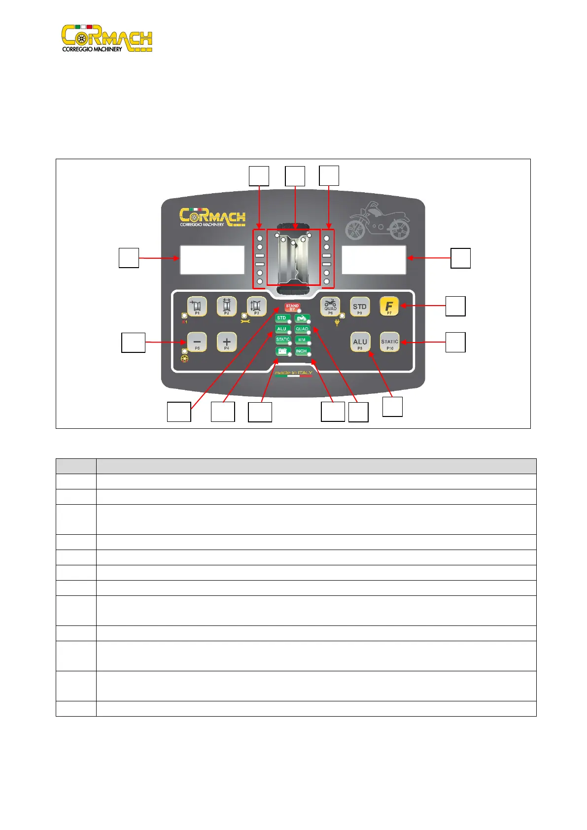
The machine control panel is shown in Figure F13.1. The control panel allows the operator to give commands and enter or edit data.
The same control panel displays the balancing results and machine messages. The functions of the various parts of the control panel
are described in table T13.1. The control panel is provided on the rear with an electronic control board collecting, processing and
displaying data.
Figure F13.1: Control panel
Table T13.1: Functions of different parts of the control panel
Display to show inside/outside imbalance value.
Light indicator showing inside/outside imbalance angular position.
3 Imbalance Weight Position light indicator. Group of 5 LEDS (red). Position depends by the Program and Wheel Type
"F" key to access the secondary function of the keys (P7).
STATIC program selection key (P10).
ALU program selection button (P8).
MOTO/QUAD selected Wheel Type light indicator (red).
10 Light indicator of the selected unit of measurement: inches/mm. Group of two light (red) indicators to indicate the
selected unit of measurement.
Charging indicator light with battery (Optional).
12 Selected Program Type light indicator (STANDARD/ALU/STATIC). Group of 3 light (red) indicators to indicate the selected
13 Example of standard key: it has a main function (big icon shown inside the key) and a secondary function (small icon
Active stand-by light indicator.