Use and maintenance manual – 10/2016 Rev. 3 Page 13
13.1 Keyboard
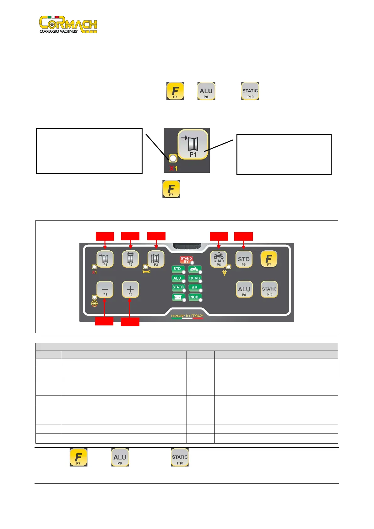
For your convenience, the keys in this manual are numbered from [P1] to [P10] as shown in Figure F13.1. Next to the reference
numbers of the keys, there are icons of the keys themselves for easy reading. The ten buttons have a main function indicated by a
symbol in the levelled square, and a secondary function indicated by a small icon located nearby. Some of the secondary functions
feature an LED to indicate their activation. The keys [P7] , [P8] , and [P10] do not have a secondary function.
The secondary function of the keys is identified in this manual with the codes from [F+P1] to [F+P9] as shown in Figure F13.3.
Figure F13.2: Key example showing the main and secondary function
To enter the secondary function of a key, press the [P7] then, by holding it down, press one of the keys for which a secondary
function is desired; then release both keys.
Figure F13.3: Key secondary functions numbering
Table T13.2: Settings, programs and menus available in SERVICE mode
[P3] Machine calibration [F+P3] Exit SERVICE mode
(return to the NORMAL mode)
Read counter with the number of launches
[P5] Inches/mm selection [F+P5] Parameters (Menu with password reserved for
Imbalance threshold view selection
Note: The [P7] , [P8] ALU and [P10] STATIC keys are not used to access settings, programs and menus.
This is the sensitive part that must
be pressed.
This section contains only a graphic
indication. An LED indicates when the
secondary function is active.