Use and maintenance manual – 10/2016 Rev. 3 Page 5
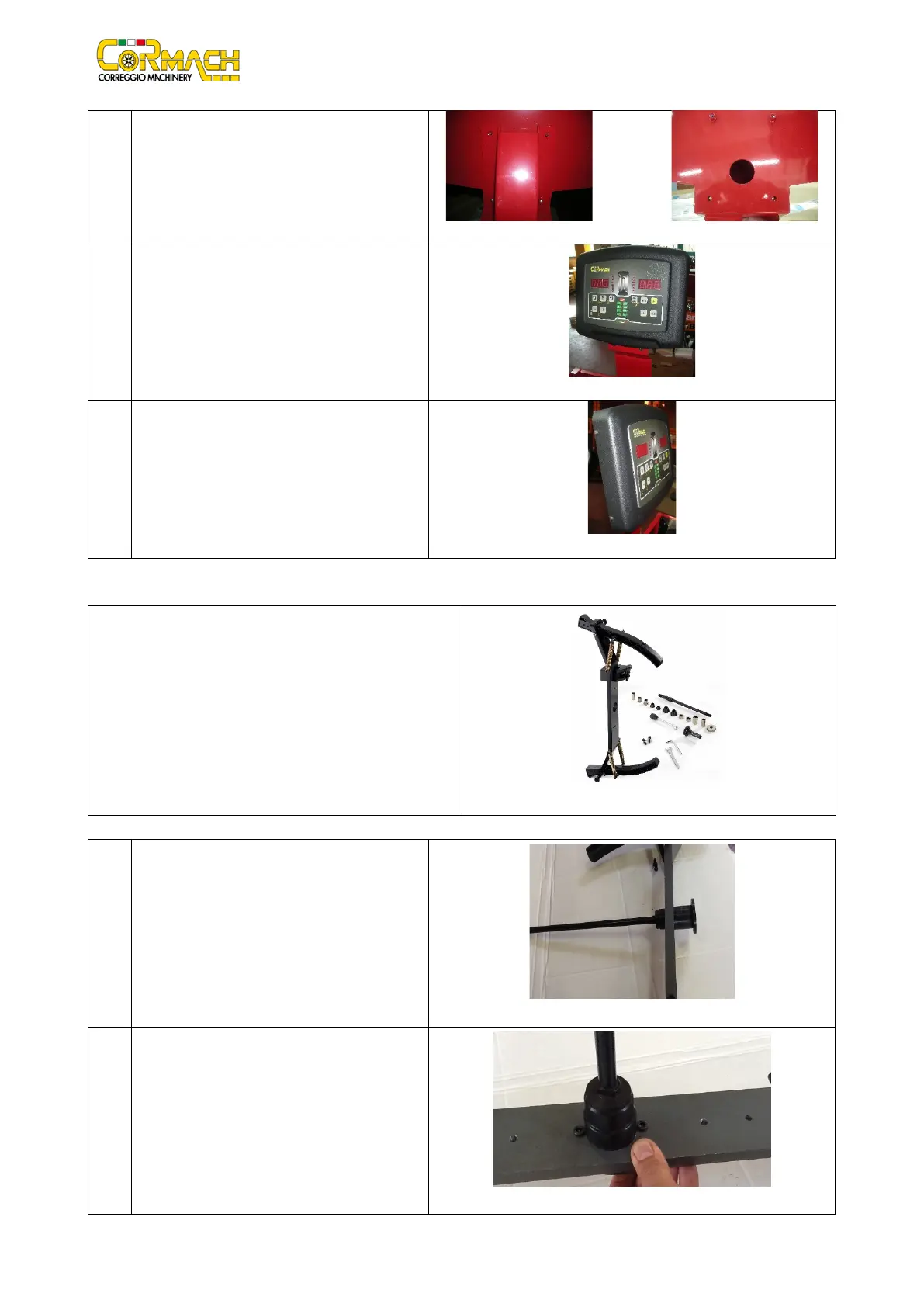
050 Secure the head to the support with the M6
screws.
060 Attach the head with its CPU board to the sheet
metal front support (Figure F6.9).
070 Secure the head with no. 4 M6 screws.
6.2 Flange for motorcycle wheel
The motorcycle flange kit is provided completed as showed in
figure F6.11. Set of:
• Nr. 1 shaft Ø 14 mm
• Nr. 2 cones Ø 14.5 ÷ Ø 25.5
• Nr. 2 cones Ø 20.5 ÷ Ø 35
• Nr. 2 bushes Ø 17 + spacers
• Nr. 1 measuring adapter
• Nr. 1 calibration weight
Assembly instructions
010 Insert the pin Ø 14 mm inside the flange (Fig.
F6.12)
020 Insert the suitable screws to lock the pin (Fig.
F6.13).