FMFV - Installation Manual
Publication Number: 919000012INS - 7 - © 2018-19, Cornelius Inc.
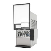
FMFV KIT INCLUDES FOLLOWING KEY COMPONENTS
INSTRUCTIONS FOR INSTALLING FMFV KIT
NOTE: Only one kit can be installed on the left side of the unit as a default position. But it can be
installed, either left or right side of the unit. One trained technician required to install FMFV Kit.
• C-Box
• UI Display
• Pump Assembly
• Valve Assembly
Table 3
Sl. No. Part Number Description QTY
1. 910002034 C-Box 1
2. 620070052 UI Display Module 1
3. 910002035 FMFV Valve Assembly 1
4. 910001938 C-Box Mounting Bracket 1
5. 910001939 C-Box Bottom Bracket 1
6. 910002047 Pump Mounting bracket 1
7.
910002209
1/4” Hose flavour pump to C-box
8
8.
910002210
1/4” Hose Y connector assembly
1
9. 910002018 Pump bracket holding 2
10. 910002017 Pump Bracket Holding bottom 2
11. 910002208 3/8” Hose with BIB connector 8
12. 910000452 Oeiteker 13.3 16
13. 910001703 Harness routing Magnet 5
14. 28301211 Inlet air Regulator 1
15. 910002060 Power Cord 1
16. 910000659 M4 X 15 Pan head screw 1
17. 910001959 Injector cap 1
18. 910001801 Display bracket 1
19. 910002053 Self tapping screw for Display 8
20. 910002080 Display bracket Magnet 1
21. 620068141 Screw 4-40 X.188” 2
22. 910001942 Cable FMFV touch Display 1
23. 910000560 Cable tie, 4 In 1
24. 910002239 Grommet Harness 1
 Loading...