Standard Recommended Procedure 003-794-AEN | Issue 14 | March 2020 | Page 12 of 27
4.7 Install EDGE™ Modules
4.7.1 Into EDGE-01U-SP, EDGE-02U and EDGE-04U Housings
Step 1: Remove the MTP®connector dust cap by pulling on the dust cap while holding the connector body.
For the initial mating, do not clean or scope connectors. Corning® CleanAdvantage™ connectors are
shipped with an optimized dust cap to maintain cleanliness for the rst use.
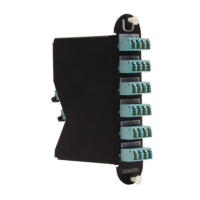
Step 2: Mate the MTP connector(s) into the adapter(s) at the back of the module (Figure 17) with the MTP key
down/opposite the module label.
Step 3: Starting with lower right corner (Tray 1, slot A), insert module from the rear until it locks into place.
Load all trays from right to left, bottom to top in the housing, as seen from the back.
Step 4: Loop slack as shown in Figure 17, leaving enough slack to pull out trays without violating the
minimum bend radius.
Step 5: Repeat for all modules.
Step 6: Loosely capture ber slack with hook-and-loop straps (Figure 17).
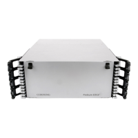
EDGE Module Installation
Figure 17 — Load EDGE Modules
CAUTION: Scoping Corning CleanAdvantage connectors increases the risk of adding contamination
to the system. CleanAdvantage technolog is designed for mating connectors without cleaning or
scoping before the initial installation.
Figure 16A