MOBILTEX® DATA LTD.
Calgary, Alberta
www.corTalk.com
TITLE: RMU1 Installation and Configuration Guide
DOCUMENT NO.:
RMU1-MAN-001
5 Installation
Warning: Only properly qualified personnel should work on installation of this equipment. Company and
industry safety procedures must be followed.
Installation consists of three steps: unit installation, wiring, and device configuration.
5.1 Unit Installation
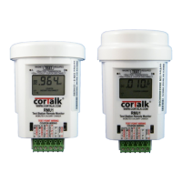
RMU1-S/RMU1-G RMU1-I #6 Screw
Figure 3 RMU1 Installation Hardware
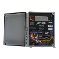
The RMU1 may be installed inside an industry standard test station, or with an optional cap, directly onto a 3” PVC
pipe. To accommodate a standard test station, a spacer ring is required to raise the test station cap enough to allow the
RMU1-S or RMU1-G to fit; for the RMU1-I, two spacer rings are needed. The spacer ring attaches to the threaded
portion of the lower test station mount. With specialized cover locking systems or for other special test station
installations, it may also be possible to cut off part of the test station terminal board to make room for the RMU1; in that
case the spacer ring would not be needed.
Figure 4 RMU1 Installed In Test Station