Do you have a question about the Cortalk RMU5 Generic and is the answer not in the manual?
Explains the meaning of terms and symbols used in the manual and on the product itself.
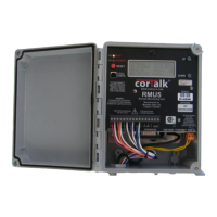
Details the RMU5 enclosure, latches, lock attachment points, and mounting plate.
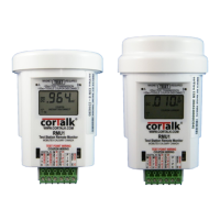
Details the LEDs, Reset button, LCD display, and control buttons on the RMU5 front panel.
Explains the function and location of various ports like GPS, Sensor Bus, Ethernet, USB, and power connectors.
Details how to mount the RMU5 enclosure using its plate, holes, or pipe clamps.
Explains the importance and procedure for connecting the protective earth terminal.
Details the connection of an external Class 2 transformer for RMU5 power supply.
Explains how to connect the GPS antenna for time synchronization.
Describes how to wire the RMU5 for measuring rectifier parameters and monitoring circuit breakers.
Discusses relay types and wiring for rectifier interruption functionality.
Details available AC solid state relays and their specifications for RMU5 installation.
Describes the mercury displacement relay option and its installation requirements.
Explains how to wire a door switch contact for monitoring by the RMU5.
Guides through installing the RMU5 configuration application and drivers on a PC.
Guides through selecting installation type and completing the RMU5 Configuration Application setup.
Details the process of installing the RMU5 USB driver, including OS prompts.
Covers launching RMUSetup, connecting via USB, and initial login procedures.
Explains how to read, edit, and write RMU5 configuration files using RMUSetup.
Details global system settings like serial number, name, logging, and reporting.
Configures network settings, MODBUS over Ethernet, and web server options.
Configures RS-232 port for various communication modes like modems and data radios.
Configures parameters for the sensor expansion bus and attached modules.
Sets up the RS-485/MODBUS serial port, including slave address.
Configures settings for the optional internal Bluetooth module, including security PIN.
Sets up rectifier interruption timing, cycle parameters, and relay control.
Configures user access levels and passwords for RMU5 security.
Configures individual I/O points, data logging, and alarm reporting parameters.
Describes system control functions and reading general status information from the RMU5.
Details how to control the rectifier output and check its status.
Lists and describes various communication protocols and hardware supported by the RMU5.
Explains how to access and use the RMU5's web server for status monitoring.
Describes the data shown on the RMU5 LCD and how to navigate through its screens.
Outlines the safe procedure for powering down the RMU5 for maintenance.
Lists and describes the pinout for the RMU5 main I/O connector.
Details the pinout for the communications expansion connector.
Lists pinouts for sensor bus, main power input, and USB host connectors.
Details pinouts for USB slave configuration and Ethernet 10/100 connectors.
Lists MODBUS registers for I/O points, alarms, and AC fail status.
Lists read-only MODBUS registers for GPS data and satellite status.
Explains how registers function based on the I/O point type for read/write operations.
| Brand | Cortalk |
|---|---|
| Model | RMU5 Generic |
| Category | Measuring Instruments |
| Language | English |