TITLE:
RMU5 Generic Installation and Configuration Guide
DOCUMENT NO.:
RMU5-MAN-001
Figure 2 shows the back and hinge side of the RMU5. The RMU5 may be mounted against a flat surface by driving
screws through the mounting hole locations shown in the picture. The RMU5 may also be mounted to a pipe using pipe
clamp bands through the slots shown in the picture.
Figure 2 RMU5 Back/Side View
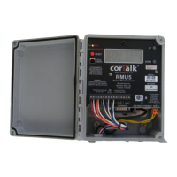
Figure 3 shows the inside of the RMU5, which includes the front panel and bottom connectors. The front panel contains
the following features:
1. Power/Fault LED Indicator. The green indicator shows when the RMU5 is powered, and if flashing red, a fault
condition is present. If main input power is interrupted, the green indicator will flash.
2. GPS/Interrupter Status LED Indicator. This bi-color indicator shows status for the optional GPS Timing
Control Module (TCM) board and also the rectifier interruption relay status. When green, the GPS TCM board