TITLE:
RMU5 Generic Installation and Configuration Guide
DOCUMENT NO.:
RMU5-MAN-001
Interrupter Relay Synchronization Signal
(RS-232 levels)
Windows CE Debug RS-232 Serial Port Receive
Data (DCE)
Windows CE Debug RS-232 Serial Port
Transmit Data (DCE)
Sensor Bus RS-485 Negative Connection
Sensor Bus RS-485 Positive Connection
GPS Synchronized One Pulse Per Second
Switched Sensor Bus 12V Power (2A max,
total power limit shared with interrupter
relay drive and main I/O +12V)
Note: Int+ (Term. Block pins 10 & 11)&
Sensor Bus power must not exceed 1.25A
combined. Do not load the 12V supply unless
the battery is fully charged.
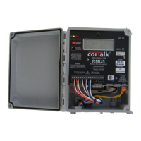
Table 5 Instrumentation Sensor Expansion Bus Connector
24VAC/DC Input #1 (DC, 50/60Hz) (This input
feeds one side of a full wave rectifier
bridge)
24VAC/DC Input #2 (DC, 50/60Hz) (This input
feeds the second side of a full wave
rectifier bridge)
Table 6 Main Power Input Connector
USB +5V Power (500mA max)
Table 7 USB Host Connector