TITLE:
RMU5 Generic Installation and Configuration Guide
DOCUMENT NO.:
RMU5-MAN-001
6.1.10.2.2 Wiring
The Sailor 3027 transceiver attaches to the DRI3 communications expansion adapter board. The adapter provides power
to the Sailor 3027 unit. Before terminating the cable, feed the cable through the cable gland on the bottom of the RMU5.
Strip the cable sheathing back approximately 15cm (6”) on the un-terminated end of the cable. The cable from the Sailor
3027 unit is then wired into the provided 4-contact Phoenix-style connector as shown in Figure 52. Apply cable-ties to
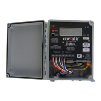
reduce strain on individual conductors. After completing wiring, plug the green 4-contact connector into the mating
socket on the DRI3 Sailor 3027 Sat Interface Board (see Figure 53).
Figure 52 Sailor 3027 Cable Termination
Figure 53 Sailor 3027 Cable Plugged Into DRI3