TITLE:
RMU5 Generic Installation and Configuration Guide
DOCUMENT NO.:
RMU5-MAN-001
has successfully attained a time lock to the NAVSTAR GPS network. When red, the rectifier output is switched
off (interrupted).
3. Reset/Power Down Button. The reset button may be held down for 10s to force a reset of the hardware on the
RMU5. The button may also be used to disengage the backup UPS battery when main power is removed.
4. Local Configuration USB Slave Port. This port is used for configuration of the RMU5 from a PC running
Microsoft Windows XP SP2 or higher. Further information on its use is located farther in this document.
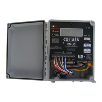
5. 20 x 4 LCD Display With Backlight. The LCD display shows the current status of the RMU5 through a paged
display system.
6. Up/Down Control Buttons. These buttons control the page being displayed on the 20 x 4 LCD display.
7. Main I/O Connector. This connector is the principle connector for the built-in analog inputs, digital input,
interrupter relay control, and RS-485 MODBUS connections. The functions of each pin are labeled on the
faceplate.
The bottom panel contains the following features:
1. GPS Antenna Connector. This connector is only present if the RMU5 is equipped with the optional internal
GPS Timing Control Module board. Attach a 3V LNA 18dB gain GPS antenna with an SMA male connector-
terminated cable to this port.
2. Sensor Bus Expansion Connector. This port is used to attach additional analog and digital I/O modules to the
RMU5.
3. Communications Expansion Connector. This connector is used to attach RS-232 communications devices such
as digital radios, MODBUS RTUs, PSTN modems, etc. Usually an adapter board will be present according to
the communications device in use.
4. USB Host Expansion Connector. Future use connector.
5. 10/100Base-T Ethernet Connector. Allows attachment to a standard twisted pair Ethernet network.
6. Main Power Input Connector. Attach a DC power source with a voltage rating of 20 to 35V, or an AC power
source with a voltage rating of 20 to 25V to this port. When connecting a DC power source, the connections
to the main power input connector are polarity insensitive. When using an AC power source, ensure that
neither connection to the main power input connector is grounded, otherwise overheating of the RMU5 internal
power supply may result. The power source should be able to deliver at least 40VA to an RMU5 that is
equipped with additional options modules. The basic RMU5 requires approximately 5VA to operate once the
internal battery is charged, and approximately 15VA while the battery is charging (with no external loads).
Wiring may be brought into the RMU5 by drilling a hole in the lower box edge and installing water tight glands or water
proof flexible conduit connectors. When drilling the holes for the feed-through connectors, avoid drilling into the RMU
aluminum chassis.
Any Interconnection wires used must be rated to 75°C or greater.