MOBILTEX® DATA LTD.
Calgary, Alberta
www.corTalk.com
TITLE: RMU1 Installation and Configuration Guide
DOCUMENT NO.:
RMU1-MAN-001
5.3 Wiring With Flex PCB Equipped Test Station
As an optional accessory, a standard test station equipped with a flex PCB that connects the RMU1 6-pin connector
directly to the test station bolts is available. All measurement sources are then connected directly to the test station bolts.
Mobiltex part number A20A04RMU01 and A20A04RMU02 are special kit configurations utilized for the monitoring
of coupons, bonds or test points. The kits consists of the following items:
A20A04RMU01
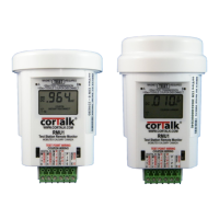
- 1pc A20A00RMU10 RMU1-S Remote Monitoring Unit for Test Stations & Coupons - Satellite 1-way
- 1pc H23530RMU01 Spacer to raise test station cap to allow RMU1 to fit inside standard test station – ORANGE
Or
A20A04RMU02
- 1pc A20A00RMU11 RMU1-I Remote Monitoring Unit for Test Stations & Coupons - Satellite 2-way Iridium
- 2pcs H23530RMU01 Spacer to raise test station cap to allow RMU1 to fit inside standard test station – ORANGE
And
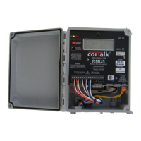
- 1pc Test Station with 8 plated screws and top cover – ORANGE
- 1pc Mobiltex FLEX3B custom interconnection Flex circuit assembly installed in above test station
- 1pc Mobiltex SLD1A Front shield board
- 1pc A20100RMU11 Rear Test Station shield for use with RMU1. Prevents user contact with test station bolts.
The following pictures illustrate the kit:
Complete unit with cover installed Cover removed – front view Cover removed – side view Cover removed – rear view
Kit components – pre-installed in the test station Rear safety shield removed Front shield and Flex circuit
Figure 15 Kit With Flex PCB Test Station