MOBILTEX® DATA LTD.
Calgary, Alberta
www.corTalk.com
TITLE: RMU1 Installation and Configuration Guide
DOCUMENT NO.:
RMU1-MAN-001
5.5 Configuration
Once the coupon or bond is wired according to one of the diagrams, the measurement type, current shunt/transformer
scaling factors (if used), and alarm limits (if used) should be programmed into the RMU1 using the RMU1PGM
configuration tool (see section 6).
5.6 Startup and Verification
All wiring should be secured and inspected before the RMU1 is powered on. The RMU1 will start operation when the
lid is screwed down. The lid should be turned an additional ½ turn after the switch click is heard in order to fully engage
the sealing gasket.
After the RMU1 is powered, observe that the RMU1 “Status” LCD indicator turns on (refer to section 5.7 for detailed
LCD operation descriptions). If the GPS receiver is enabled in the configuration, the RMU1 will display the ‘GPS’ icon
on the LCD display and also show a number in the format of ‘X.YY’ where X is the number of satellites being received
and YY is the average signal strength of those satellites. The RMU1 will not send a power-up message or display
measurements on the LCD screen until GPS signal acquisition is complete.
Note that transmissions from RMU1-S field devices typically require from <1 minute (good antenna view of the sky) to
30 minutes (poor antenna view of the sky) to arrive at corView. The delivery variability is because the RMU1-S transmits
the message a total of three times (for airtime plans with periodic reporting intervals greater than 6 hours) to help insure
a high message delivery success rate, even under partially degraded sky view conditions. The first transmission occurs
within seconds of the measurement cycle. Each of the two retransmissions occurs between 5 and 10 minutes of the prior
transmission. Transmissions from RMU1-I and RMU1-G devices should be received usually in less than one minute.
If the RMU1 programming interface is attached to the RMU1 at power-up, the power-up message will be delayed by 5
minutes.
Place a magnet at the point labelled “TEST” on the RMU1 for between 1s and 5s to initiate an immediate measurement
cycle and “Button Press” exception transmission to the corView web host. Note that a maximum of 6 “Test”
transmissions are allowed during a 12-hour period. Test transmissions are only possible after the initial RMU power-
up message has been sent to corView.
The actual measurement readings from the site should appear on corView shortly after the message was transmitted.
CorView can be configured to automatically send emails containing the measurement readings to an individual or group
of email users. Because these emails are short and wireless-friendly, many clients send the readings directly to their
field installers wireless email device(s) for near immediate end-to-end operation confirmation and verification of
measurement values. Alternatively, the measurement readings can be locally retrieved and displayed using the
RMU1PGM configuration tool. It is good practice to confirm that all the measurements are as expected and that they
are not too close to any programmed alarm limits (if utilized).
The installation and site should be inspected a final time before properly securing the equipment and leaving the site.
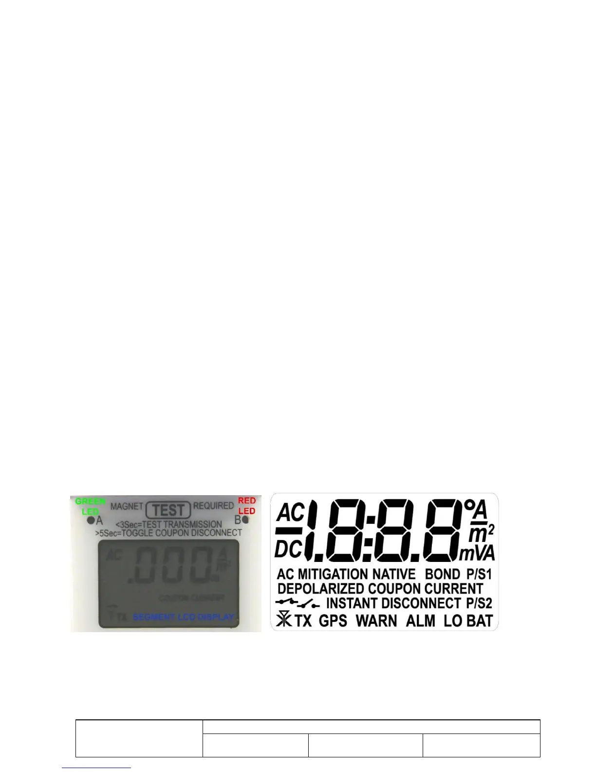
5.7 Status Display
Figure 23 RMU1 Segment LCD and LED Status Indicators
The RMU1 has a segmented LCD display and two LED indicators (A and B, see Figure 23) that provide status
information to the user. The LCD and LEDs function as follows:
The LED indicators are currently only used by the firmware loader function. They should remain off during normal
operation.