31
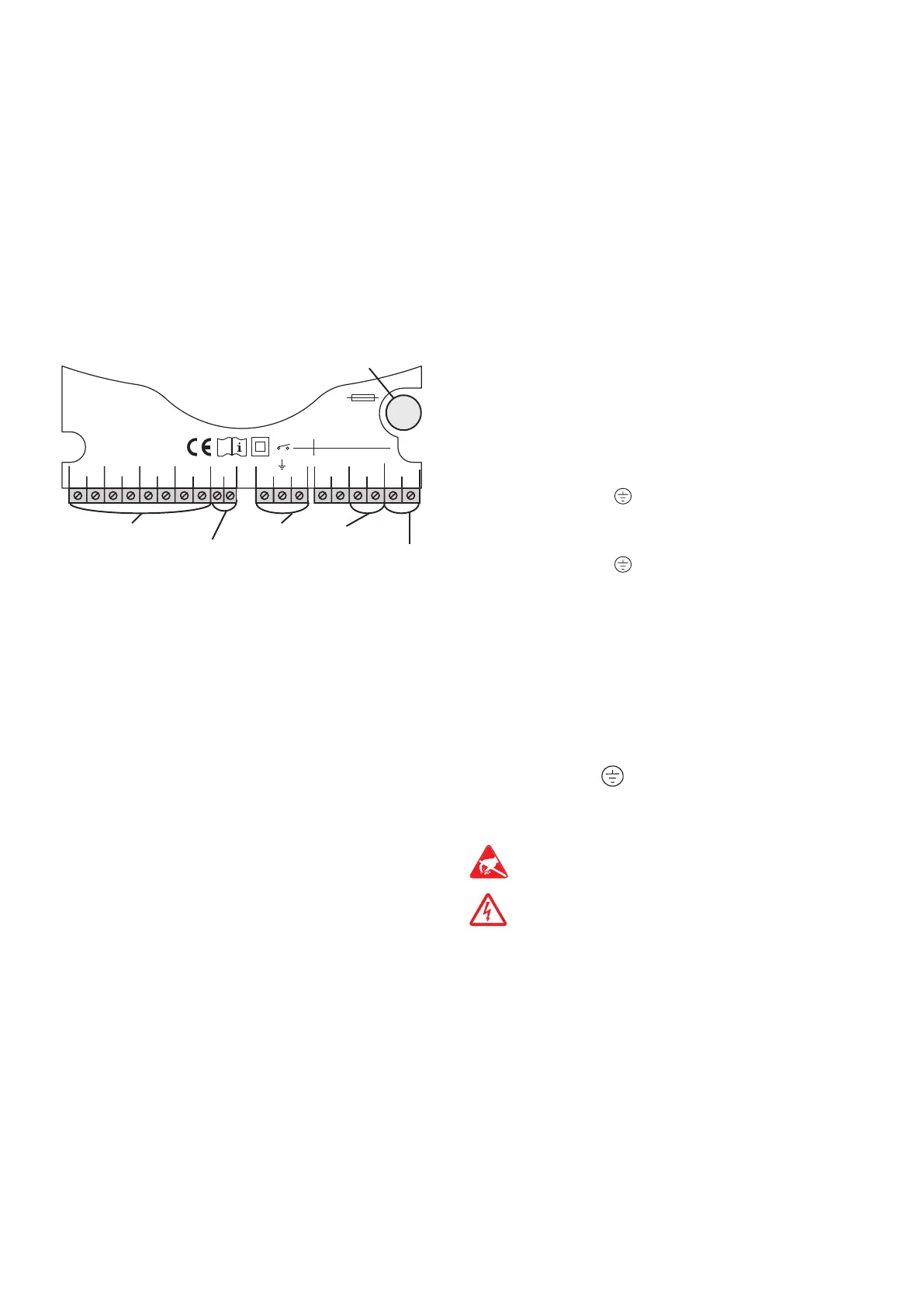
1.2 Electrical connection
The power supply to the controller must be carried
out via an external power switch (last step!) and the
supply voltage must be 220 ... 240 V~ (50 ... 60 Hz).
Flexible cables must be attached to the housing with the
enclosed strain relief and the corresponding screws.
The controller is equipped with 2 relays to which loads
such as pumps, valves, etc. can be connected:
• Relay 1
18 = conductor R1
17 = neutral conductor N
13 = ground clamp
• Relay 2
16 = conductor R2
15 = neutral conductor N
14 = ground clamp
Temperature sensors (S1 to S4) have to be con-
nected to the following terminals (either polarity):
1 / 2 = sensor 1 (e.g. sensor collector 1)
3 / 4 = sensor 2 (e.g. sensor store 1)
5 / 6 = sensor 3 (e.g. store top sensor)
7 / 8 = sensor 4 (e.g. return temperature sensor)
The powersupplyconnectionhas to be carried out
via the following terminals:
19 = neutral conductor N
20 = conductor L
12 = ground clamp
mains terminals
fuse
load terminals
sensor terminals
ground terminals
Electrostatic discharge can lead to damage to
electronic components!
Dangerous voltage!
1 2
S1 S2 S3
3 4 5 6
Temp. Sensor
Pt1000
LNR1N
R1-V
N
201918171615
S4
7 8
141312
T4A
1 (1) A (220 ... 240) V~
2 (1) A (220 ... 240) V~
R1
R1-V
VBus
9 10
VBus
®
connection clamps
1. Installation