32
VBus
9 10
R1-V
S1
S2
S4 / TRF
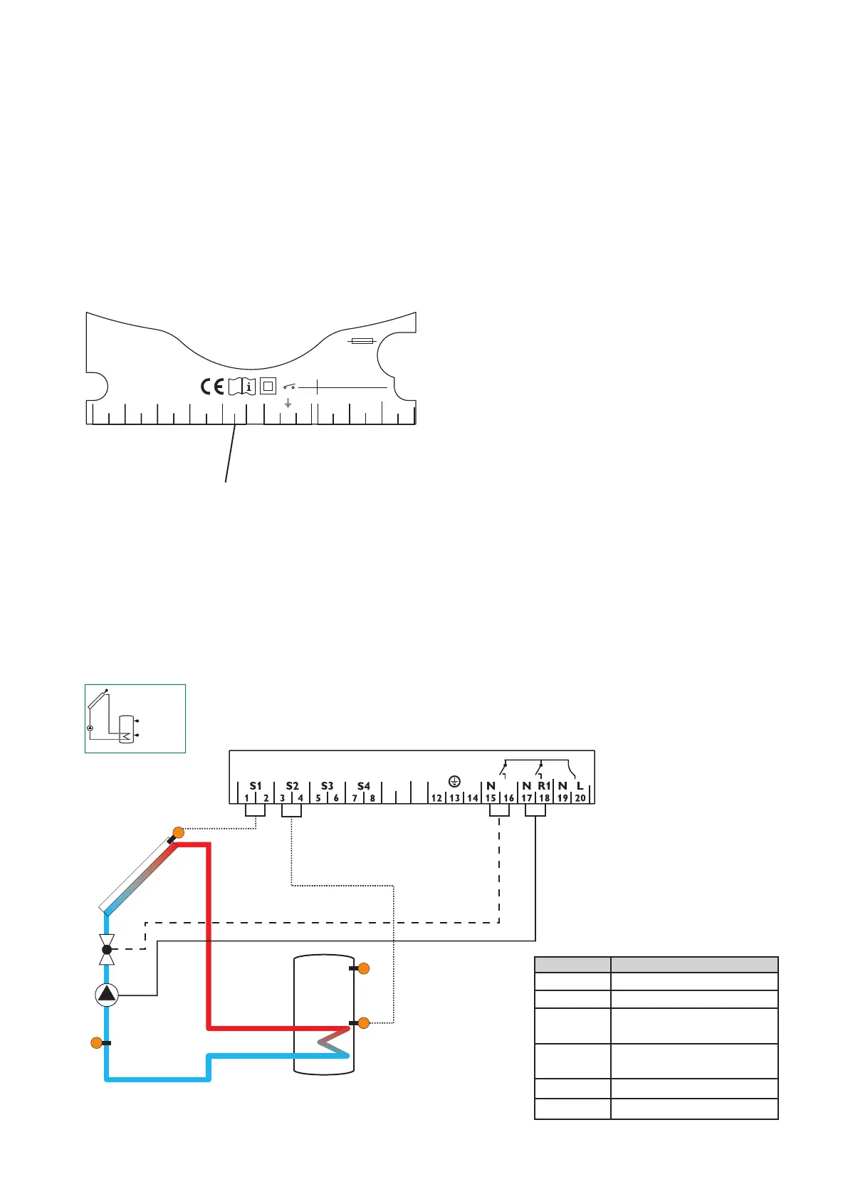
1.2.2 Allocationofterminalsforsystem1
Standardsolarsystemwith 1 store, 1 pump and 3
sensors. The sensor S4 / TR can be optionally used for
heat quantity measurement.
R1
S3
Symbol Specication
S1 collector sensor
S2 store base sensor
S3 store top sensor,
(optional)
S4 / TR sensor for heat quantity
measurement (optional)
R1
solar pump
R1-V
valve (optional)
1.2.1 Data communication / Bus
The controller comes with a VBus
®
for data commu-
nication and energy supply of external modules. The
connection is effected with optional polarity at the
clamps marked with„VBus“. Via this data Bus you can
install one or more VBus
®
modules, e.g.:
• large display GA3 / SD3
• Data logger, DL2
• Data teleindication
Additionaly, the controller can be connected to the PC
with the help of a RS-COM adapter. With the Service-
Center Software (RSC) the controller parameters can be
changed, measurements can be read out, processed
and visualised. The software enables an easy function
control and adjustment of the system.
VBus
®
connection clamps
1 2
S1 S2 S3
3 4 5 6
Temp. Sensor
Pt1000
LNR1N
R1-V
N
201918171615
S4
7 8
141312
T4A
1 (1) A (220 ... 240) V~
2 (1) A (220 ... 240) V~
R1
R1-V
VBus
9 10
1. Installation
R1-V