GND
S1
CS10
S8
S10
V40
R7-A
R7-M
R7-R
R6
R5
R1
R2
R3
R4
S9
S7
S6
S5
S4
S3
S2
Sensors
Bus
VBus
floating relay
semiconductor relay
OK / Set
R1-R6
1 (1) A (100 ... 240) V~
4 (1) A (100 ... 240) V~
R7
Netz / Mains
100 ... 240 V~
50-60 Hz
T4A
IP 20
L' LN
SW 2.0
Vor Öffnen Gerät spannungslos
schalten!
Isolate mains before removing cover!
Masse-Sammelklemme benutzen
Use the ground common terminal block
Neutralleiter.
Sammelklemme benutzen!
Use neutral conductor
collective block
Erdungsleiter-Sammel-
klemme benutzen!
Use ground common
terminal block!
GND
PWM1
PWM2
PWM3
GND
GND
12
34 5
6
COSMO GmbH
D-22549 Hamburg
Multi 2
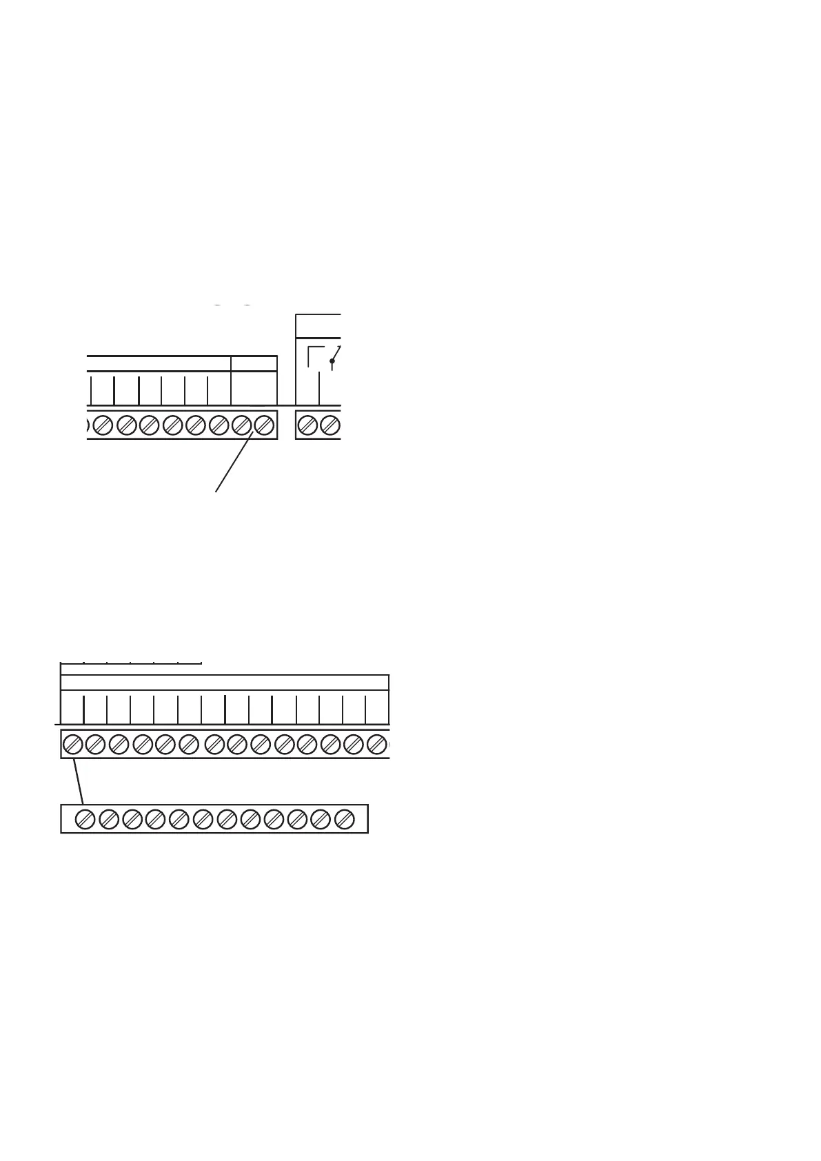
1.2.3 Data communication / bus
The controller is equipped with the VBus
®
for data trans-
fer with and energy supply to external modules. The
connection is carried out at the two terminals marked
“VBus
®
“ (either polarity). One or more VBus
®
modules
can be connected via this data bus:
• WMZ, calorimeter
• large display / Smart Display
• Datalogger
• COSMO heating circuit modules HKM
(up to 3 modules)
VBus
terminals
1. Installation
1.2.4 Sensors
GND
S1
CS10
S8
S10
V40
R7-A
R7-M
R7-R
R6
R5
R1
R2
R3
R4
S9
S7
S6
S5
S4
S3
S2
Sensors
Bus
VBus
floating relay
semiconductor relay
OK / Set
R1-R6
1 (1) A (100 ... 240) V~
4 (1) A (100 ... 240) V~
R7
Netz / Mains
100 ... 240 V~
50-60 Hz
T4A
IP 20
L' LN
SW 2.0
Vor Öffnen Gerät spannungslos
schalten!
Isolate mains before removing cover!
Masse-Sammelklemme benutzen
Use the ground common terminal block
Neutralleiter.
Sammelklemme benutzen!
Use neutral conductor
collective block
Erdungsleiter-Sammel-
klemme benutzen!
Use ground common
terminal block!
GND
PWM1
PWM2
PWM3
GND
GND
12
34 5
6
COSMO GmbH
D-22549 Hamburg
Multi 2
ground-common terminal block
The controller is equipped with 12 sensor inputs in
total. The ground connection for the sensors has to be
carried out via the ground terminal block (GND).
• Temperature sensors have to be connected to the
terminals S1 ... S10 and GND (either polarity)
• The irradiation sensor (CS10) is to be connected to
the terminals CS10 and GND with correct polarity.
Connect the terminal GND of the sensor to the termi-
nal GND of the controller (ground terminal block), and
the terminal CS of the sensor to the terminal CS10 of
the controller.
• A flowmeter V40 can be connected to the terminals
V40 and GND (either polarity).
69