relay allocation
sensor allocation
sen.1 sen.2 sen.3 sen.4 sen.5 sen.6 sen.7 sen.8 sen.9 sen.10 V40
Tkol
Tspu
DVGW
Th 1
Tby
T-WT
T1DT5
Th 2
Tsp2u
T2-DT5
Tsp3u Tsp4u
Th 7
T1-DT8
Sen1 RMS
Th 8
T2-DT8
Sen2 RMS
Th 9
T1-DT9
T1 WMZ
Sen3 RMS
Th 10
T2-DT9
T2 WMZ
Sen4 RMS
WMZ
relay 1 relay 2 relay 3 relay 4 relay 5 relay 6 relay 7
solar pump st1 solar pump st2
func. bl. 1
HSE
bypass
par. relay
ext. HE
solar pump st3 solar pump st4
func. bl. 4
store load.
RMS-Mi open
func. bl. 5
message rel.
AH suppress.
RMS-Mi closed
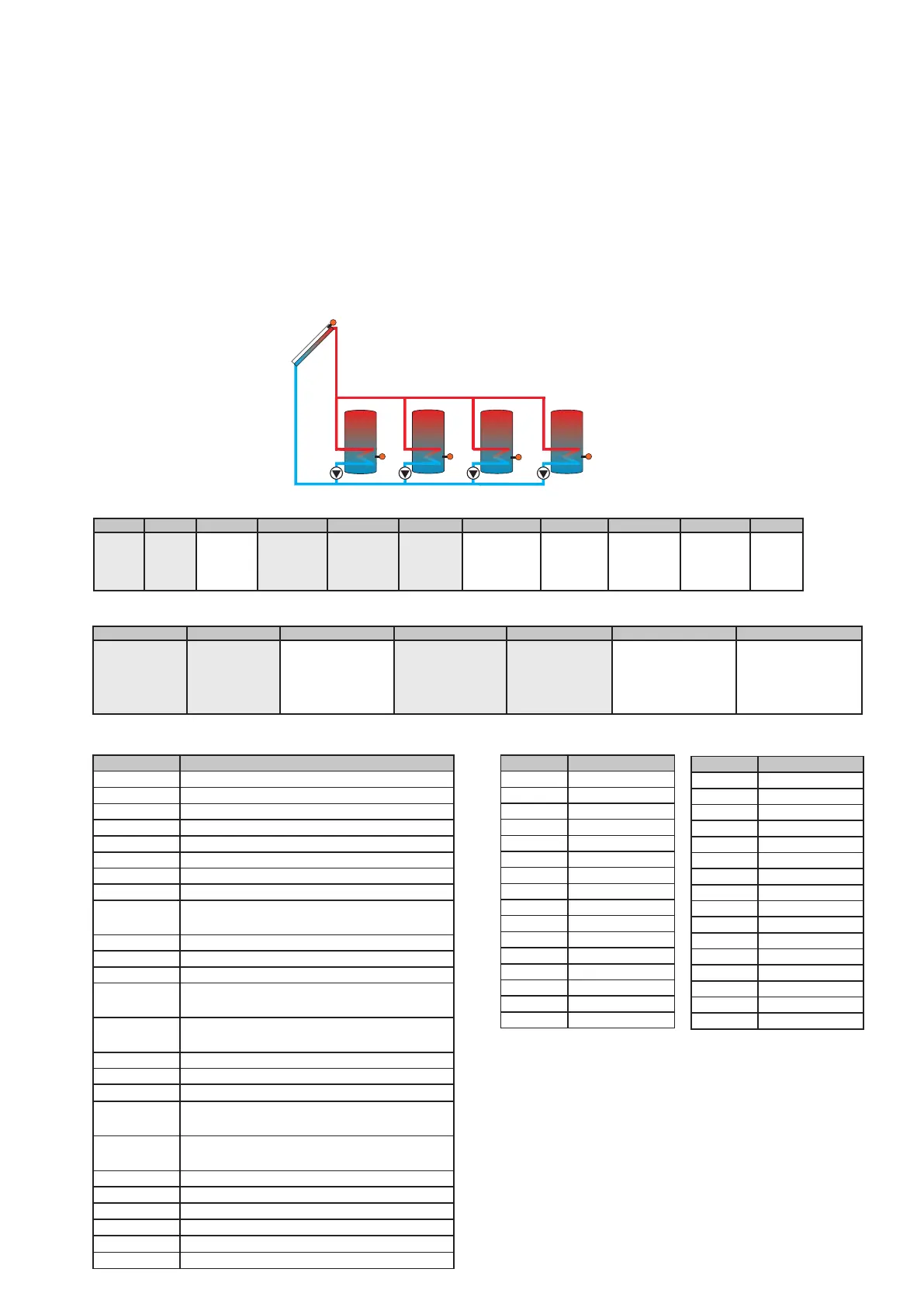
System 7 variant 2
sensor denomination
Tcol temperature-collector
Tcol2 temperature-collector 2
Tstb temperature-store 1 base
Tst2b temperature-store 2 base
Tst3b temperature-store 3 base
Tst4b temperature-store 4 base
T-HE temperature-heat exchanger
Tby temperature-bypass
HSE temperature- protection against legio-
nella
Th 1-10 temperature-thermostat 1-10
T1-DT5-9 temperature- DT5-9 high
T2-DT5-9 temperature- DT5-9 low
T1-AH-HC temperature- afterheating-heating
circuit
T2-AH-HC temperature- afterheating-heating
circuit
HC T-FL temperature- heating circuit flow
HC T-outd. temperature- heating circuit outdoors
HC RTA11 heating circuit remote control
T1 WMZ temperature- flow heat quantity
measurement
T2 WMZ temperature- return heat quantity
measurement
WMZ flowmeter
Sen 1 RMS Store temperature
Sen 2 RMS Return temperature unmixed
Sen 3 RMS Return temperature mixed
Sen 4 RMS Outdoor temperature RMS
TDHW DHW store zone temperature
Abbreviations - sensors
sensor location
1 Multi
2 Multi
3 Multi
4 Multi
5 Multi
6 Multi
7 Multi
8 Multi
9 Multi
10 Multi
11 Flow HC
12 1. HKM (S1)
13 1. HKM (S2)
14 1. HKM (S3)
15 1. HKM (S4)
16 1. HKM (S5)
sensor location
17 1. HKM (S6)
18 Flow 1. HKM
19 2. HKM (S1)
20 2. HKM (S2)
21 2. HKM (S3)
22 2. HKM (S4)
23 2. HKM (S5)
24 2. HKM (S6)
25 Flow 2. HKM
26 3. HKM (S1)
27 3. HKM (S2)
28 3. HKM (S3)
29 3. HKM (S4)
30 3. HKM (S5)
31 3. HKM (S6)
32 Flow 3. HKM
Sensor allocation
Sensors 1-10 are the sensors connected to the controller.
Sensors 12-32 are the sensors connected to the additi-
onally connected heating circuit modules.
Sensors 11, 18, 25 and 32 show the calculated flow set
temperature respectively.
3. Commissioning
S1
S5
S2
S4
R2
R4
S6
R1
R5
88