All diagrams are for general information. Consult installation instructions for details.
5
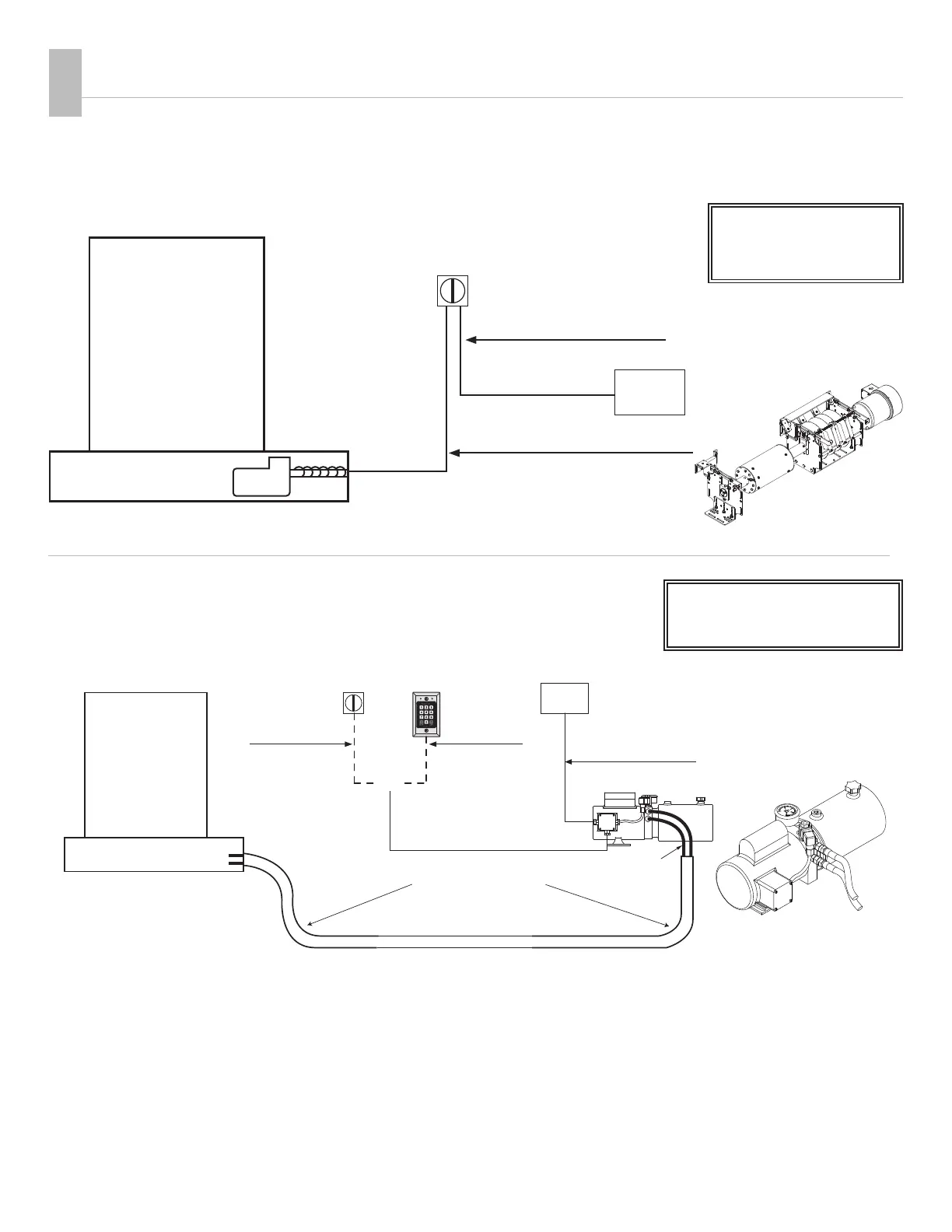
Electric Motor w/ Keyswitch (Standard Equipment)
¾ hp Motor with Slip Clutch
Hydraulic Power System
(Optional)
3" poly or PVC pipe from
housing to power unit.
NO SHARP BENDS!
ELECTRICAL
Choose electric or hydraulic power and controlling devices.
All switches must be
mounted in full view of
the cover operation.
hydraulic motor
050275 or 050276
Hydraulic Pump Unit
electric motor
3
WARNING! These are minimum recommendations only. All local and federal codes of standard safe practices
must be followed. Refer to the prewiring instructions for detailed instructions and additional mounting options.
Dedicated
GFCI
Key Switch 120V
(Hot, Neutral, Ground)
(Neutral, Dir 1, Dir 2, Ground)
Pool
Cover Housing
NPT watertight connector 14 AWG Min.
Wire extended 8" past conduit end.
Conduit with three different
colored wires and one ground.
Conduit to 120 VAC 15
AMP dedicated G.F.C.I.
WARNING! These are minimum recommendations only.
All local and federal codes of standard safe practices must be followed.
36" of waterproof flex conduit with 1/2"
14 AWG under 50ft
12 AWG over 50ft
14 AWG under 50ft
12 AWG over 50ft
MOTOR
POOL
COVER HOUSING
HYDRAULIC MOTOR END
HYD PUMP UNIT
CONDUIT FOR HYDRAULIC HOSE
WITH SWEEPING BENDS
LARGE SWEEPING BENDS
Conduit to HYD pump J-box with
2 identified wires and 1 ground
Conduit With (3)
12 AWG (min)
Identified Wires
plus one ground
Conduit with (4)
18 AWG (min)
Identified Wires
for CoverLink
Wired Control
Option 1:
Key Switch KOSA
Green
LED
Red
LED
Option 2:
CoverLink
Wired Control
OR
two 1/2" hoses
over 80'
Dedicated
GFCI
14 AWG under 50ft
12 AWG over 50ft
All switches/control pads must
be mounted in full view of the
cover operation.
Hydraulic motors must be
mounted above ground level.