CowTech Ciclop 3D Scanning Guide
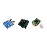
Click accept if the results seem
reasonable. Each colored plane in the
diagram represents a one of the nine
orientations of the calibration pattern.
Laser Triangulation
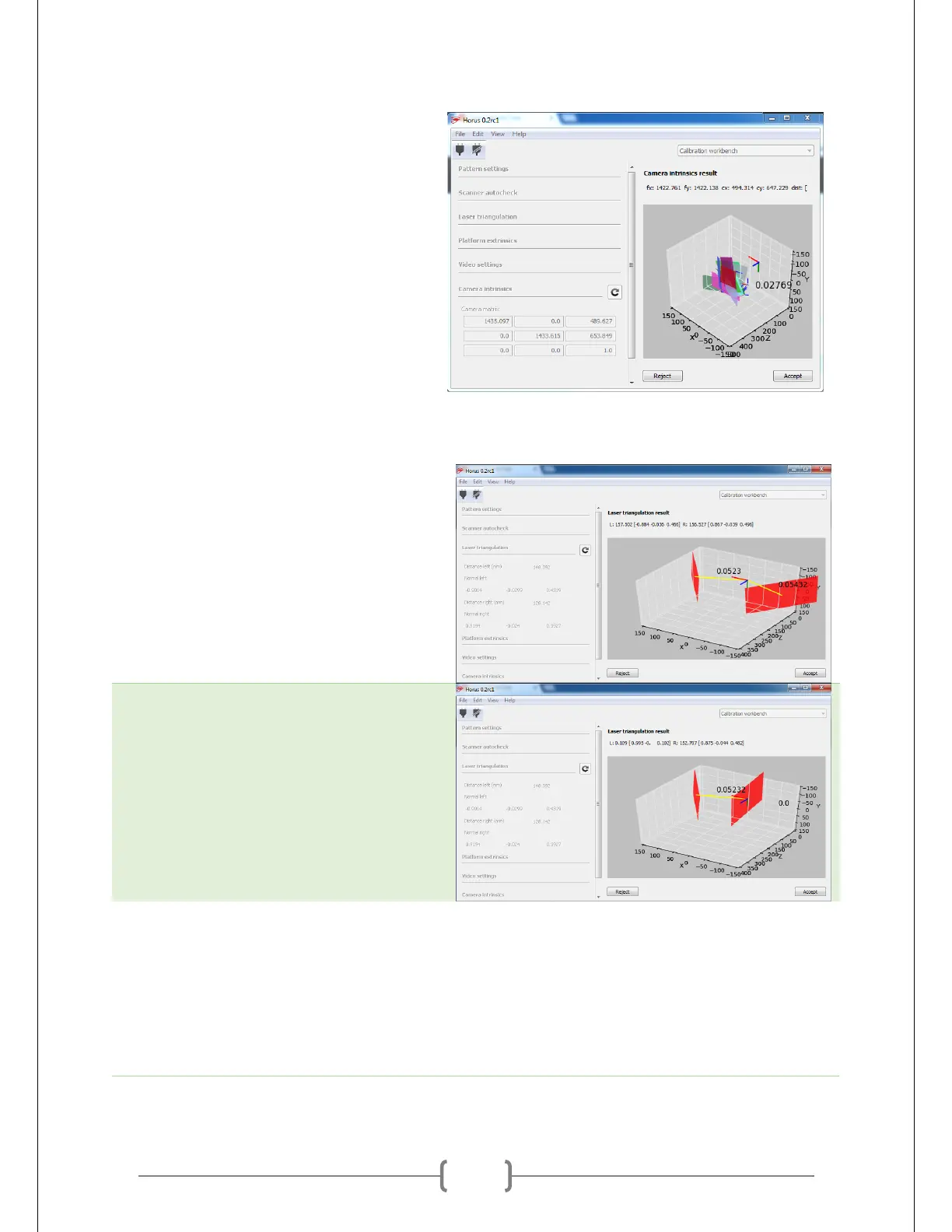
Run the Laser Triangulation calibration.
Make sure you have the pattern on the
table when you do. The result should look
similar to what is shown at right. The two
numbers floating next to the red planes
should be somewhere between 0.05 and
0.06.
If those numbers are off, the scanner isn’t
properly detecting the laser. Readjust your
settings for Calibration Segmentation and
try again. You can see an example of a bad
triangulation on the right.
Platform Extrinsics
Run the Platform Extrinsics calibration. If
Laser Triangulation worked without a
problem, this should work fine as well. It
will spin the table and record a number of
frames at different angles.