1018028-BPage 11
FIG. 9
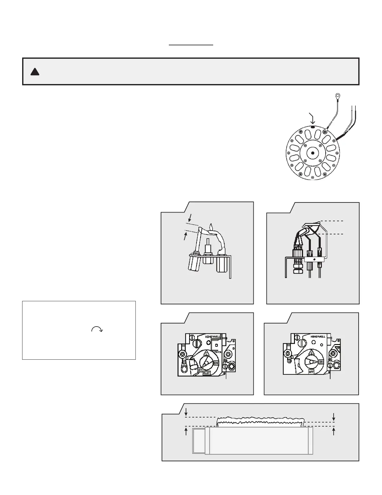
MAINTENANCE
PILOT ADJUSTMENT
1.
the valve.
2.
(pilot generator)(see
Figure 8).
operating at inlet line pressure (Max.
7” w.c. for Natural Gas and 11” w.c. for
Propane).
MANUAL RESET SWITCH
For your safety this furnace is equipped
before unsafe temperatures are reached.
manually reset. If outages persist, call a
TO DECREASE
THE PILOT FLAME
(Approximately six full turns to bottom of pilot
light channel)
For proper and safe operation, keep furnace and furnace area clean. At regular intervals turn
the vent system, pilot and burner operation prior to use each year.
(See Figure 7).
Examine the venting system as a routine part of the safety performance check on an
annual basis.
OIL
TUBE
FIG. 7
FIG. 8-A
Standing Pilot
Pilot flame should envelop 3/8 to
1/2 inch of the tip of sensor.
3/8”-1/2”
FIG. 8-D
Pilot Adjustment Screw
IID Pilot
FIG. 8-C
Pilot Adjustment Screw
Standing Pilot
1-1/2”
3/4”
WARNING: This is a gas-red appliance. Keep the area clear of gasoline and other ammable vapors
and liquids. All combustible material must be kept clear of this area to avoid re or explosion.
!
FIG. 8-B
IID Pilot
Pilot flame should envelop 3/8 to
1/2 inch of the tip of sensor.
3/8”
to
1/2”