1018028-BPage 7
FIG. 5
LOCATIONS
cause pilot outage.
possible in the area to be heated.
10” maximum. For proper combustion, make sure unit is level front
to back and side-to-side.
the furnace could be isolated from the space to be heated by closing
a door.
(See Figure 2a)
installation of the furnace or vent tubes.
7. Be sure to maintain adequate accessibility clearances for servicing
and proper operation.
8. If the furnace is installed in a basement, a 12” clearance must be
INSTALLATION
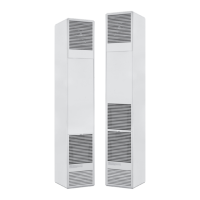
ELECTRICAL ROUGH-IN
on the left side terminating in a receptacle box (not provided). Consult
Dimensions).
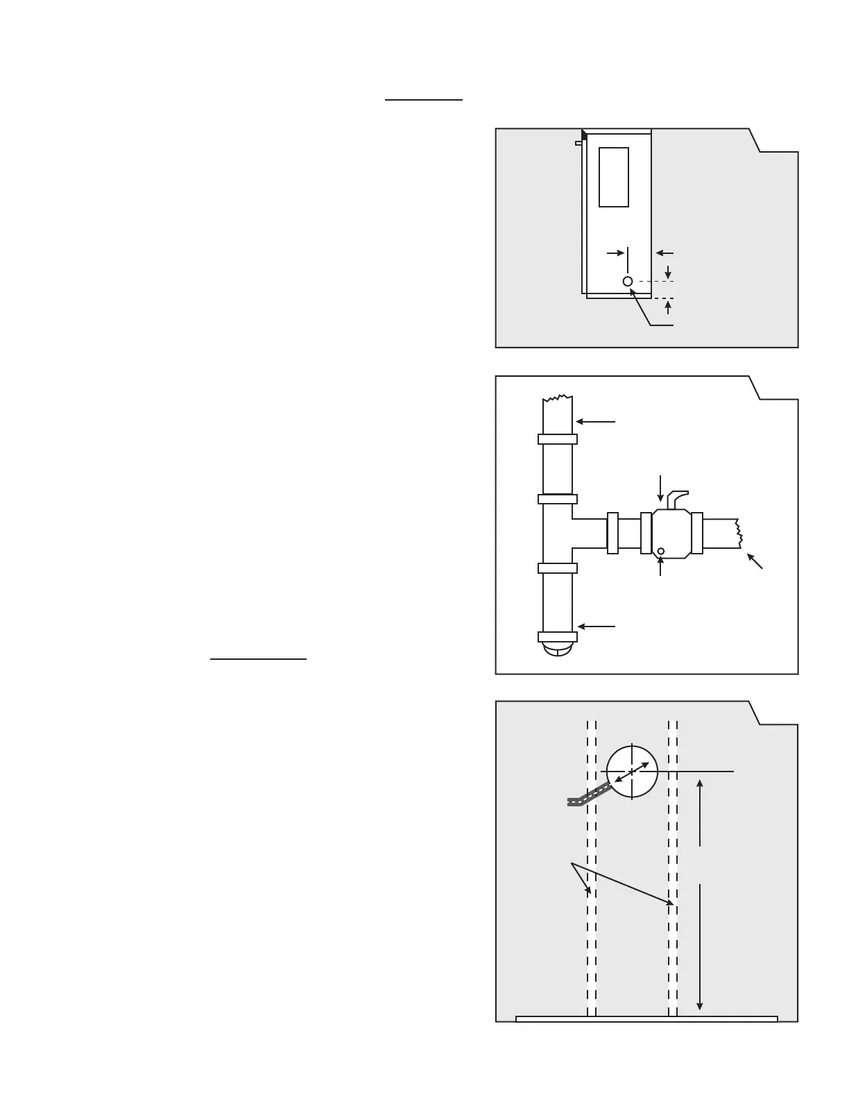
ROUGH-IN GAS SUPPLY
Install a 1/2 inch diameter gas supply line. The gas line can enter the
cabinet through the right side or bottom (See Figure 3). The gas line
drip leg and provide a 1/8” N.P.T. plugged tapping, accessible for test
gauge connection, immediately upstream of the gas supply connection
to the furnace (See Figure 4).
the gas supply piping system during any pressure testing of that system
at test pressures in excess of ½ psig (3.5kPa). The furnace must be
isolated from the gas supply piping system by closing its individual
piping system at test pressures equal to or less than ½ psig (3.5kPa).
FIG. 3
MANUAL CUT-OFF VALVE
1/8” NPT
GAS
SUPPLY
LINE
FIG. 4
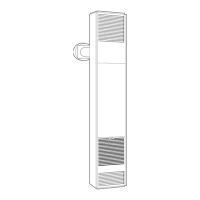
WALL
STUDS
DVCF40 - 59”
DVCF55 - 68-1/2”
FINISHED
FLOOR
9-1/4
DIA.