• Ensure the mounting location is away from RF interfering materials and objects such as
reflective surfaces, brick and concrete, microwaves, and so on.
• Pre-drill holes for the mounting screws.
• Use anchors and other screw-securing accessories to ensure the device is securely mounted in
place.
• Refer to the Location Considerations section of this document.
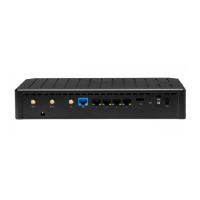
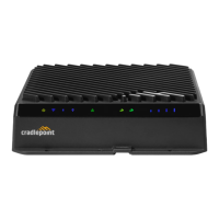
STEP 8 (Optional): Connect the Ethernet cable.
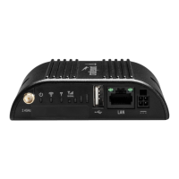
o If you are using a wired, Ethernet WAN connection, connect the Ethernet cable to the WAN port
on the back of the R1900. Connect the other end to your WAN source.
o If you are using a wireless WAN (using cellular connectivity), you will need to power up the
router first, access your NetCloud Manager account, and then complete the setup.
STEP 9: Power up the router.
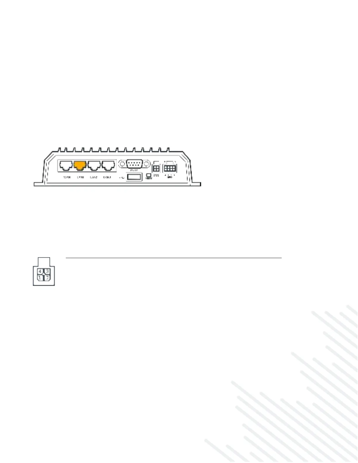
The 4-pin GPIO cable is configured to allow for using a 4-wire/GPIO cable to hardwire power for DC
connections, or for using GPIO. Refer to the following for pin configuration:
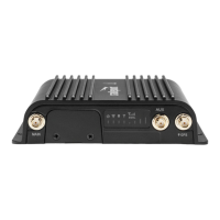
• Insert the 4-pin end of the power adapter into the 4-pin port on the router, ensuring appropriate
alignment of pins as illustrated above.
• Connect the wires on the other end to the appropriate fuse or power source.
• Allow 1 minute for the router to run through its bootup sequence.
Ground to the vehicle chassis
VDC ignition sensing accessory input
General purpose I/O (GPIO)
 Loading...