21
Figure 32
To access the dust hood, remove the
storage box (B) shown in figure 31
above, clean and remove dust and
debris from the dust hood (C) in figure
33.
Figure 33
Maintenance & Adjustments
45 & 90 Deg, Bevel Stop
Adjustments
1. Be sure to disconnect the
machine from the power source.
2. Raise the blade to its highest
position and then lift the blade
guard.
3. Loosen the bevel lock knob on
the tilting hand wheel, turn the
hand wheel clockwise until it
stops.
4. Check the angle of the blade with
a combination or machinists
square from the left side of the
blade, keeping the square flat
against the table and flat part of
the blade. DO NOT touch the
teeth or the table insert with the
square.
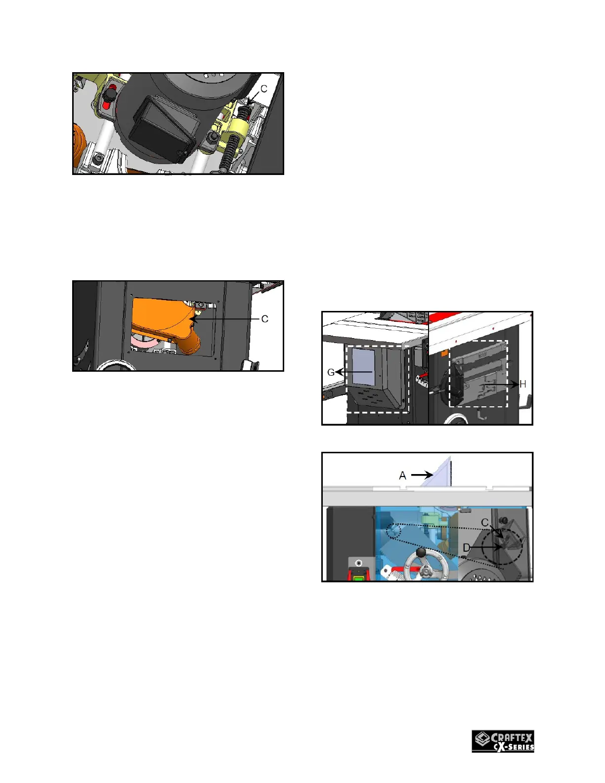
If the blade is at the correct angle at 90
degrees, remove the motor cover (G)
figure 34 then loosen the hex nut (C)
figure 35. Turn the 90 Deg. Stop screw
(D) figure 35 under the table with a hex
wrench. Then turn the hand wheel until
the blade is at 90 Deg to the table
surface. Re-tighten the 90 Deg. Stop
screw and Hex Nut until a slight
resistance is felt. Do not over-tighten.
Figure 34
Figure 35
You can verify the 45 Deg. setting by
tilting the as far as possible to the left
and using the combination square,
check the angle. If needed adjust as for
the 90 Deg. Stop. In this case remove
the storage box (H) figure 36 and loosen
the Hex Nut (E), figure 36. Turn the 45
 Loading...