4
DM-RMC-4K-SCALER-C/-DSP: 4K DigitalMedia 8G+ Receivers Supplemental Guide – DOC. 7728A
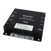
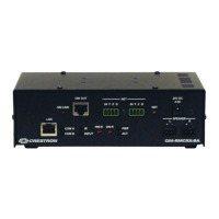
Side View, Right
The following illustration shows the right side of the DM-RMC-4K-SCALER-C.
8-pin RJ-45 female, shielded, with two LEDs;
10BASE-T/100-BASETX Ethernet port;
Green LED indicates Ethernet link status;
Amber LED indicates Ethernet activity
Do not connect the LAN port to an Ethernet switch if the DM IN port connects
to a DigitalMedia switcher.
19-pin Type A HDMI female;
HDMI digital video/audio output (DVI compatible)
HDMI OUT requires an appropriate adapter or interface cable to accommodate
a DVI signal. CBL-HD-DVI interface cable is available separately.
Green LED, indicates video signal presence at the HDMI output
8-pin RJ-45 female, shielded, with two LEDs;
DM 8G+ input, HDBaseT
®
standard compliant;
PoDM+ PD (Powered Device) port;
Connects to the DM 8G+ output of a DM
®
switcher, transmitter, or other DM device, or
to an HDBaseT device via CAT5e, Crestron DM-CBL-8G, or Crestron DM-CBL-ULTRA
cable;
Green LED indicates DM link status;
Solid amber LED indicates HDCP video;
Blinking amber LED indicates non-HDCP video
Receiving PODM+ requires connection to a switcher or other equipment that
has a PoDM+ PSE (Power Sourcing Equipment) port. Any wiring that is connected to a
PoDM+ PSE port is for intrabuilding use only and should not be connected to a line that
runs outside of the building in which the PSE is located.

 Loading...