Crestron DMPS-100/200/300-C/300-C-AEC DigitalMedia Presentation System
Operations Guide – DOC. 7219D DigitalMedia Presentation Systems: DMPS-100/200/300-C/300-C-AEC • 25
Connectors, Controls & Indicators (Continued)
# CONNECTORS
1
,
CONTROLS &
INDICATORS
DESCRIPTION
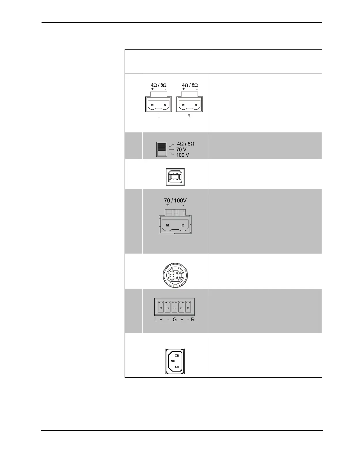
27 SPEAKER OUTPUT
(2) 2-pin 7.62 mm 15A detachable terminal
blocks;
4-8 Ω stereo speaker-level audio output;
Wire size: Terminals accept up to 14 AWG
Output power: 20W RMS per channel stereo
at 8 Ω, 4 Ω tolerant;
Driven by program audio output
NOTE: 4 Ω/8 Ω and 70/100V outputs are
mutually exclusive.
28 SPEAKER OUTPUT
(1) 3-position slide switch, selects the
amplifier output configuration
29 SERVICE
(1) USB Type B female, for factory use only
30 SPEAKER OUTPUT
(1) 2-pin 7.62 mm 15A detachable terminal
block;
Transformer-isolated 70 or 100 volt mono
speaker-level audio output;
Wire size: Terminals accept up to 14 AWG;
Output power: 40 W RMS mono at 70 or 100
volts;
Driven by program audio output
NOTE: 4 Ω/8 Ω and 70/100V outputs are
mutually exclusive.
31 PoDM
(1) 4-pin snap & lock power jack;
48 volt power input for PoDM power pack,
sold separately;
Enables Power over DM
32 PROG OUT
(1) 5-pin 3.5 mm detachable terminal block;
Balanced/unbalanced stereo line-level audio
output;
Output impedance: 200 Ω balanced, 100 Ω
unbalanced;
Maximum output level: 4 Vrms balanced, 2
Vrms unbalanced
33 100-240V – 4.0A
50/60 Hz
(1) IEC C14 male chassis plug, main power
input;
Mates with removable power cord, included
(Continued on following page)


 To Next Page