Page 18
CE-Series
Amps with an Attitude!
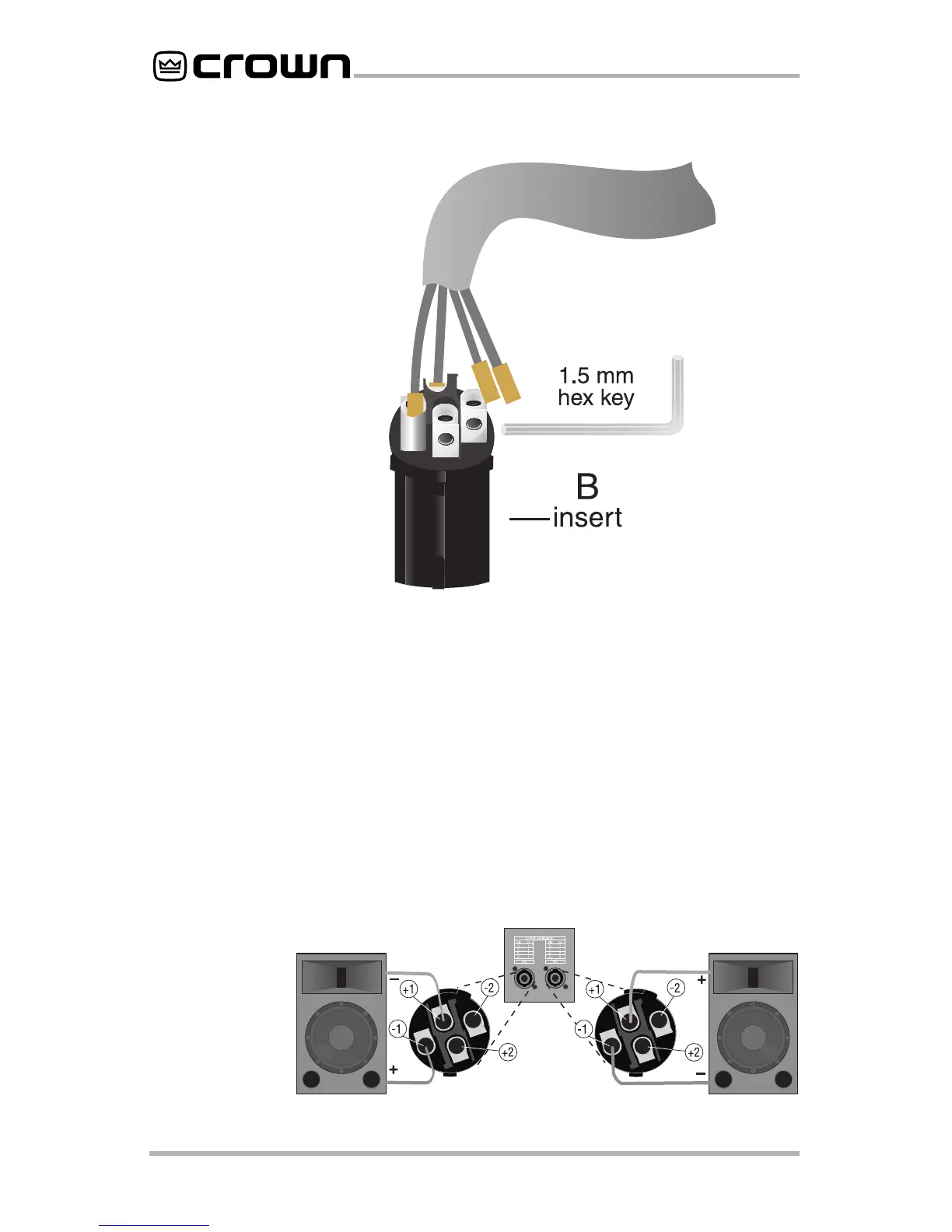
priate slot of the connector insert (B) as shown in Figure
2.6. Use a 1.5-mm hex key inserted into each side slot to
tighten the connection.
2.6.4a—If the Mode switch is in the “Stereo” position (for
stereo configuration),
connect the positive (+) and nega-
tive (–) leads of each wire to the appropriate Channel 1
and Channel 2 connectors as shown in Figure 2.7. Refer
to Figure 2.10 for complete system setup. You may use all
4 poles of the Channel 1 output connector to feed both
speakers, if you wish.
Fig. 2.7
Stereo Output
Wiring
Fig. 2.6
Wiring for
the Neutrik
Speakon
NL4FC
Connector

 Loading...