Page 45
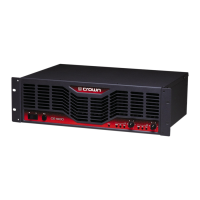
CE-Series
Amps with an Attitude!
Controls
Level: A detented rotary level control for each channel located
on the front panel.
Power: An on/off rocker switch located on the front panel.
Input Sensitivity: A two-position switch located on the back
panel near the input connectors. Can be set to 1.4 V for full
output into an 8-ohm load or a fixed voltage gain of 26 dB.
Mode: Turn power off before switching. A switch located on
the back panel below the input connectors which, when turned
to stereo, operates the amplifier as two independent channels.
When “Bridge-Mono” mode is selected, the amplifier bridges
the two output channels for twice the output voltage..WATCH-
OUT SPEAKERS!!
Indicators
Signal: A green LED for each channel which flashes when a
very low-level signal (>–40 dBm) is present at input. May be
used for troubleshooting cable runs.
Clip: A red LED for each channel which turns on when
distorion becomes audible in the amplifier output.
Fault: OFF is good. This red indicator will blink under three
different conditions:
1. When the amplifier is first powered up, until the unit is
ready for operation.
2. If the heatsinks reach a temperature above normal work-
ing limits.
3. If the transformer thermal protection circuit is activated.
4. If amplifier output wires develop a short-circuit.
5. Should the amplifier output stage become non-opera-
tional.
This circuit may be monitored remotely by plugging into the
back-panel RJ11 jack (Fault), and using a circuit like the one
described in Figure 5.2. Under some conditions, the output of
the amplifier will be muted.
Power: A green LED that turns on when the amplifier has been
turned on and has power.

 Loading...