Page 5
Micro-Tech 600/1200/2400 Power Amplifiers
ILLUSTRATIONS
1.1
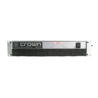
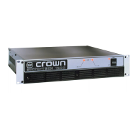
Micro-Tech
Amplifier .................................................................. 7
2.1 Front Facilities ............................................................................ 8
2.2 Rear Facilities ............................................................................ 9
3.1 Mounting Dimensions .............................................................. 10
3.2 Top View of a Rack-Mounted Unit............................................. 10
3.3 Proper Air Flow with a Rack-Mounted Blower ........................... 10
3.4 Stereo Wiring ........................................................................... 11
3.5 Bridge-Mono Wiring ................................................................. 12
3.6 Parallel-Mono Wiring ................................................................ 13
3.7 Unbalanced Input Wiring for the Optional
MT-XLR ...................
14
3.8 Balanced Input Wiring for the Optional
MT-XLR........................
14
3.9 Balanced and Unbalanced Phone Plug Wiring......................... 14
3.10 Subsonic Filter Capacitors ....................................................... 15
3.11 Unbalanced RF Filters.............................................................. 15
3.12 Balanced RF Filters .................................................................. 15
3.13 Wire Size Nomograph .............................................................. 16
3.14 Low-Frequency Protection Circuit for Inductive Loads ............. 17
3.15 Loudspeaker Fuse Nomograph ............................................... 18
3.16 AC Mains Cords and Plugs ...................................................... 18
4.1 Indicators ................................................................................. 19
4.2 Input Sensitivity and Ground Lift Switches................................ 21
5.1 Circuit Block Diagram .............................................................. 23
6.1
Micro-Tech 600
Minimum Power Matrix .................................... 27
6.2
Micro-Tech 1200
Minimum Power Matrix .................................. 28
6.3
Micro-Tech 2400
Minimum Power Matrix .................................. 28
6.4
Micro-Tech 600
Maximum Power Matrix ................................... 29
6.5
Micro-Tech 1200
Maximum Power Matrix ................................. 30
6.6
Micro-Tech 2400
Maximum Power Matrix ................................. 30
6.7 Typical Frequency Response ................................................... 31
6.8 Typical Damping Factor ........................................................... 31
6.9 Typical Output Impedance ....................................................... 31
6.10 Typical Phase Response .......................................................... 32
6.11 Typical Crosstalk for the
Micro-Tech 600 ..................................
32
6.12 Typical Crosstalk for the
Micro-Tech 1200 ................................
33
6.13 Typical Crosstalk for the
Micro-Tech 2400 ................................
33
7.1
Micro-Tech 600
Power Draw, Current Draw and Thermal
Dissipation at Various Duty Cycles ........................................... 34
7.2
Micro-Tech 1200
Power Draw, Current Draw and Thermal
Dissipation at Various Duty Cycles ........................................... 35
7.3
Micro-Tech 2400
Power Draw, Current Draw and Thermal
Dissipation at Various Duty Cycles ........................................... 35
8.1
MT-XLR ....................................................................................
36
8.2
MT-BB ......................................................................................
36