CHAPTER 9 8354/8404
9-6
D615-W02 May-2003
21
22
23
615W906A
615W905A
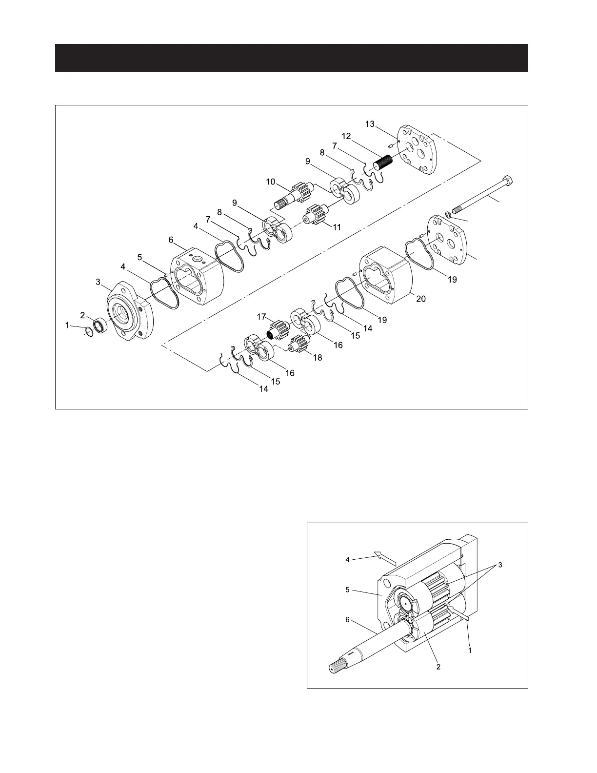
4.1 STRUCTURE OF HYDRAULIC PUMP
4.2 OPERATION
A. The hydraulic pump provides constant oil flow to
operate the steering wheel and hydraulic cylinder.
The hydraulic assembly consists of two pumps hav-
ing different displacements.
B. Two pumps operate equally and use a outside gear
design to move the amount of fluid determined at
each rotation and positive displacement.
C. Oil inflow and outflow continues while driving hy-
draulic pump from engine cam shaft, drive gear and
rotating pump gear (3). When gear is disconnected,
the vacuum will be made to enable oil inflow (1) to
pump. As gear rotated, oil continues to flow.
(1) Snap Ring
(2) Bearing
(3) Cover (Front)
(4) Seal Ring
(5) Pin
(6) 1st Pump
(7) Seal Ring
(8) Seal Ring
(9) Bushing
(10) Drive Gear Shaft 1
(11) Passive Gear 1
(12) Coupling
(13) Cover
(14) Seal Ring
(15) Seal Ring
(16) Bushing
(17) Drive Gear Shaft 2
(18) Passive Gear
(19) Seal Ring
(20) 2nd Pump
(21) Cover
(22) Spring Washer
(23) Bolt
(1) Inflow to Pump (4) Outflow From Pump
(2) Bushing (5) Pump Housing
(3) Gear (6) Drive Shaft
4. HYDRAULIC PUMP
www.mymowerparts.com
K&T Saw Shop 606-678-9623 or 606-561-4983
 Loading...