8-12 Periodic Maintenance and Adjustment
injection volume in order for the engine to
operate smoothly. The adjustments are
based on the temperature of the cooling
liquid
.
Ignition signal
Ignition signals emitted from the magneto
provides the ECU with correct ignition timing.
ECU
The ECU is the core of the EFI system. It
uses a specially designed micro computer
chip as a controller. Based on the input from
sensors, as conditions change the controller
ensures accurate control of the fuel volume
delivered by the fuel injector nozzle. This
enables the EFI engine to provide fuel
efficient low emissions performance
.
EFI System inspection
If the EFI system fails, the meter will display
the appropriate failure code. You can also
use the special EFI system failure diagnostic
tool. This electronic tool can provide more
detailed failure information than the
speedometer. The electronic tool is equipped
with its own user manual and is available
through authorized dealers.
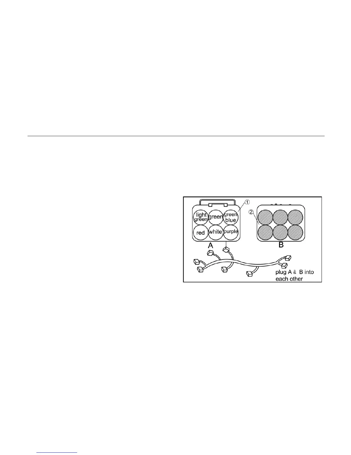
1. Diagnostic apparatus cable 2. EFI cables

 Loading...