Cuda 2412 • 8.914-384.0 • Rev. 5/12
OPERATOR’S MANUAL
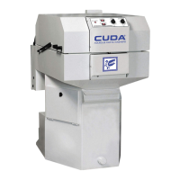
AUTOMATIC PARTS WASHER
8
SECTION 2: INSTALLATION
BEFORE YOU BEGIN
To prepare to install the machine, choose an unob-
structed, level site that allows convenient access for
operators and maintenance personnel. Sources for
water and electrical power should be located near the
installation site. If your machine is equipped with
the optional power brush and hand detail brush
you must also run a compressed air line to the
installation site.
If you have any questions regarding the installation,
please contact your distributor and have the machine
identification number available for the distributor to
reference. Your machine identification tag is located
inside the front cover of this manual for detailed machine
specifications.
STEP 1: MAKE ELECTRICAL
CONNECTIONS
NOTE: All electrical installation tasks must be per-
formed by a licensed, professional electrician to ensure
safe and proper operation. The installation must comply
with the National Electric Code and all applicable state
and local codes.
The machine can only operate on the type of electri-
cal power indicated on the machine identification tag.
Read and understand the machine identification tag
to determine the electrical power requirements before
installing the machine.
STEP 2: CONNECT A
COMPRESSED-AIR LINE AND
ACCESSORIES (OPTIONAL)
This step is required for machines equipped with
the optional power brush and hand detail brush.
If your machine does not have these options,
skip the following procedure.
NOTE: To ensure proper operation and to minimize
the possibility of premature component failure, make
sure the compressed air is supplied at 75 to 90 psi.
We also recommend an in-line moisture trap and
an in-line lubricator on the main air supply line.
Refer to the documentation provided with the power
brush for more information.
Step 1:
Remove the power brush from the box, install the wire
brush in the chuck, and connect the air hose.
Step 2:
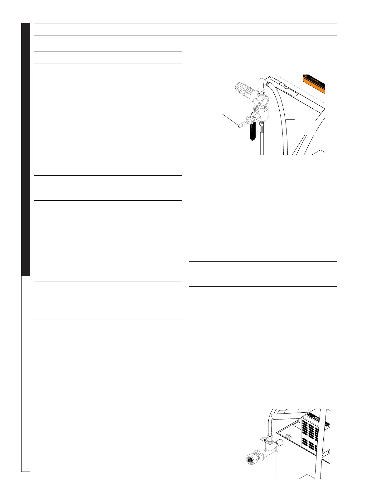
Familiarize yourself with the three-way air flow valve
(See Figure Below), then install a fitting (if necessary)
to accommodate a connection to your compressed-air
supply.
Step 3:
Connect the shop compressed-air line to the
machine.
Step 4:
Connect the hose from the power brush to the air flow
valve.
Step 5:
Hang the power brush on the bracket mounted along
the right side of the machine.
STEP 3: CONNECT A
WATER LINE
This step is required for machines equipped with the
optional automatic water fill feature. If your machine
does not have this option, skip this step.
The optional automatic water fill feature automatically
maintains the correct water level in the sump. The fea-
ture requires that you connect the machine to a dedi-
cated water supply line.
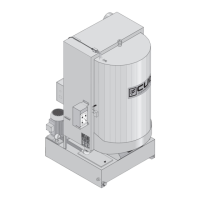
To connect the machine to a water supply line, attach a
suitable burst-proof hose to the hose connection on the
rear of the machine (See Figure Below), then connect
the hose to a nearby water spigot.
NOTE: The machine is designed for portability, and
some maintenance tasks require that you move the
machine. DO NOT make a permanent connection from
your shop water supply to the machine.
To Power Brush
Connection
Line to
Detail
Brush
Pump
Compressed
Air
Connection
Hose
Connection
(Optional)