CUH CUH CUH CUH CUH CUH CUH
CUH CUH CUH CUH CUH CUH CUH CUH CUH CUH CUH CUH CUH CUH CUH CUH CUH CUH CUH CUH CUH
CUH CUH CUH CUH CUH CUH CUH CUH CUH CUH CUH CUH CUH CUH CUH CUH CUH CUH CUH CUH CUH
CUH CUH CUH CUH CUH CUH CUH CUH CUH CUH CUH CUH CUH CUH CUH CUH CUH CUH CUH CUH CUH
CUH CUH CUH CUH CUH CUH CUH CUH CUH CUH CUH CUH CUH CUH CUH CUH CUH CUH CUH CUH CUH
CUH CUH CUH CUH CUH CUH CUH CUH CUH CUH CUH CUH CUH CUH CUH CUH CUH CUH CUH CUH CUH
CUH CUH CUH CUH CUH CUH CUH CUH CUH CUH CUH CUH CUH CUH CUH CUH CUH CUH CUH CUH CUH
CUH CUH CUH CUH CUH CUH CUH CUH CUH CUH CUH CUH CUH CUH CUH CUH CUH CUH CUH CUH CUH
CUH CUH CUH CUH CUH CUH CUH CUH CUH CUH CUH CUH CUH CUH CUH CUH CUH CUH CUH CUH CUH
22
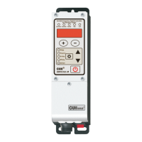
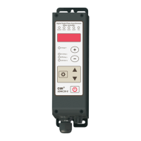
SDVC31 Series
Variable Frequency Digital Controller for Vibratory Feeder
SDVC31SMSEN_4.012023-08
The controller can set the logical relation of the Intelligent Photoelectric
Sensor and the Switch Sensor when they work simultaneously.
Variable Frequency Digital Controller
for Vibr
atory Feeder
Variable Frequency Digital Controller
for Vibratory Feeder
Variable Frequency Digital Controller
for Vibratory Feeder
Saturated
Saturated
Saturated
Accelerate
Accelerate
Accelerate
Remote
Remote
Remote
Stop
Stop
Stop
Lock
Lock
Lock
Voltage
Voltage
Voltage
Frequency
Frequency
Frequency
On Delay
On Delay
On Delay
Off Delay
Off Delay
Off Delay
Soft Start
Soft Start
Soft Start
SDVC31-M
SDVC31-M
SDVC31-M
8Long press and ▲
simultaneously to enter the
advanced parameter interface.
Short press to switch to 8
Parameter Π.
8Press ▲ or ▼ to adjust the
parameter value.
OR
AND
XOR
Default Logical Relation is AND.
Logical Relation: AND :
The controller runs only when both the
Intelligent Photoelectric Sensor and the
Switch Sensor ask the controller to.
Logical Relation: OR :
The controller runs when the Intelligent
Photoelectric Sensor or the Switch Sensor
asks the controller to.
Logical Relation: XOR :
The controller runs only when the
Intelligent Photoelectric Sensor and the
Switch Sensor output the opposite control
signal.
5.4 Logical Relation Setting of the Control Signal
 Loading...