10
Ref. H.3
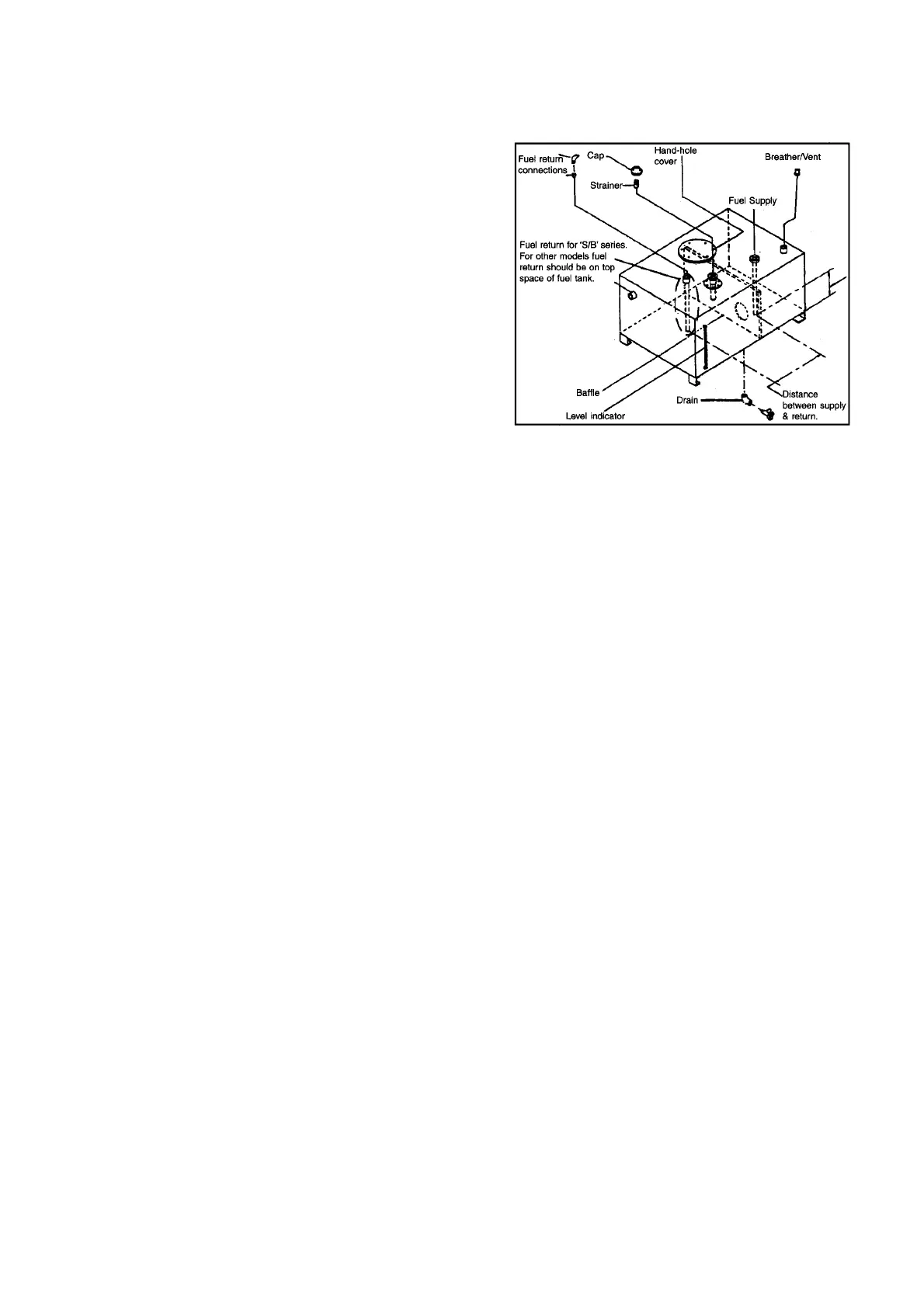
H.3 Fuel tank design requirements
• Size to suit atleast one shift operation or maximum
990 ltrs. (Material MS for fuel tank and piping)
• Drain fittings to bleed water condensate at lowest
point of tank.
• Fill neck to be provided to allow min. 5% expansion
space.
• Breather is mandatory.
• Use pipe sealant Loctite Type 577 for all connections,
for sealing. No teflon tape to be used.
• Suction and return line to be separated by at least
300 mm.
• Galvanizing not recommended, inside fuel tank.
• Hand hole, Wire mesh filter screen at filling point.
4. 1st stage regulator
5. 2nd stage regulator
6. Carburettor
The fuel system for gas engine includes following :
1. Manual shut-off valve (Main line Valve)
2. Gas Filter
3. Gas shut-off valve (Electrical)
H.4 Schedule B MS pipe should be used for fuel piping from fuel tank upto the engine. Flexible hoses supplied with
the engine should do the terminal connection between MS pipe and engine.
H.5 Fuel piping should be free from leaks. GI and copper pipes react with diesel and can’t be used.
H.6 Please refer Table 1 for recommended fuel line sizes for fuel piping lesser than 10 m. If piping length is
more than 10 meters, contact OEM / Cummins for detail engineering.
H.7 Fuel tank location should be such that it does not obstruct free movement of service personnel or ventilation air.
GAS ENGINES FUEL SYSTEM RECOMMENDATIONS
With the increased availability of Natural Gas all over the country, more and more customers are opting for Gas
Gensets. As such it is necessary to have a brief overview of the various components used in the gas supply line prior
to getting connected to the gas engines.
Various components used in gas supply piping to the engine inlet and installation recommendations are as follows :
• Fuel suction pipe should be 50 mm (2") inside the bottom of the fuel tank for B Series and above engines. For
S3.8 engine 25 mm (1”) is acceptable.
• For PT fuel system, fuel return line should be on top of fuel level and for X / S / B / C series engines
with high pressure fuel system fuel return should be dipped in fuel.