17
M.4 While terminating R.Y.B. phase notations should be
maintained in the alternator and control panel for easy
maintenance.
M.5 Crimped cables should be connected to alternator and
control panel through cable glands.
M.6 Overheating due to loose thumbing / undersize cables
causes most of electrical failures, hence ensure that
correct size of cables and thimbles is used.
M.7 For AMF application, use 8/10 core 2.5 sq. mm armoured
copper cable for control cabling.
M.8 Typical cable sizes for 415 V application are provided
in Table M.7. The sizes given are indicative, please
refer to cable manufacturers for details.
M.9 For HT installations, kindly contact OEM’s for details
on sizing.
M.10 Care to be taken, that weights of cables should not fall
on alternator / base rail. It is recommended to support
output cables on separate structure on ground.
M.11 External wirings, when provided for remote voltage /
excitation monitoring / droop CT etc. shall be screened
sheathed type. Maximum length of such wiring shall
not exceed 5 meters.
N Earthing
N.1 The generating set and all associated equipment, control
and switch gear panels must be earthed before the set
is put into operation.
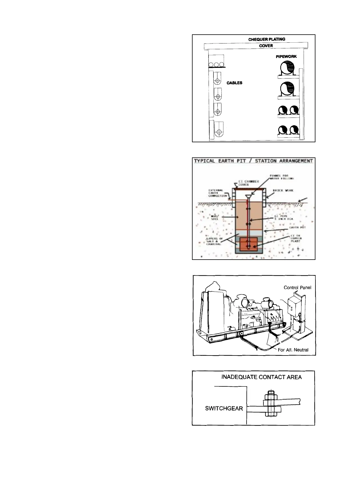
N.2 4 numbers earth pits are required as per Indian Electricity
rules or local electricity board.
- 2 earthing pits for genset / control panel body
- 2 earthing pits for neutral
N.3 Copper or GI strips of suitable size may be used for
earthing. Please note that for normal soil, earth
resistance should not exceed one ohm.
Earthing should be checked with multimeter (one
probe at genset / Alternator / baserail and another
at earth strip. The resistance should be less than
1 ohm.
For gensets with AVM’s between engine / alternator
and base rail. The earthing MUST be done at the engine /
alternator and NOT at baserail.
N.4 Genset should be earthed at two distinct points through
a conductor heavy enough to carry the short circuit
current without burning out.
O. Alternator Termination Links
O.1 For proper terminations between links and switchgear
terminals, the contact area must be adequate. The
following situations should also be avoided as they lead
to creation of heat sources at the point of termination :
- Point contact arising out of improper positioning of
links with switchgear terminals (Ref. O.1).
Ref. N.4
Ref. N.2
NORMAL
FLOOR
LEVEL
Ref. O.1
Trench Construction