16
Cosine of angle Ø is the power factor.
Voltage
Current
L.8 Please refer Table L.8 for details and CT Ratios to be
used with PCC1 (PCC3100) controls.
L.9 Gensets above 500 kVA has option of “Power
Command Control (PCC)” for genset control. 500 kVA
to 1500 kVA gensets can be supplied with PCC 3100
(PCC-1) and 1875 / 2000 kVA gensets with QSK 60
engines can be supplied with PCC 3200 (PCC-2).
AMF Operation :
There are three types of AMF operations as below :
A) Operational system is automatically restored to operation
within 10 seconds after interruption of normal power source
- with sudden load on the engine. This operation exerts a
‘Thermal shock’ to the engine. For example UPS.
B) Operational system is automatically restored to operation
within 10 seconds after interruption of normal power source
- but with gradual load (in steps) on the engine with low
initial load. There is no ‘Thermal shock’ to the engine.
C) Operational system is manually restored to operation after
interruption of normal power source - with gradual load on
the engine. There is no - ‘Thermal shock’ to the engine.
No changes in engine are required for AMF operations
described in B and C above.
For ‘A’ type of AMF operation :
No oil heaters are required, coolant heaters are required.
(For details contact OEM / Cummins.)
Power Factor (P.F.)
Power Factor is the cosine of the angle between current vector
and the voltage vector.
The power factor of the electrical system depends upon the
nature of characteristics of the load. e.g. Induction motors,
Furnaces etc.
• PF is lagging for inductive load.
• PF is leading for capacitive load.
• PF is unity for (purely) resistive loads.
If the PF of the load is less than the standard (0.8) the alternator
gets overloaded.
If the PF of the load is more than the standard (0.8) the engine
gets overloaded.
If the PF is low, then use capacitor banks of suitable capacity
to improve the power factor.
For current at various power factors, refer Table-4.
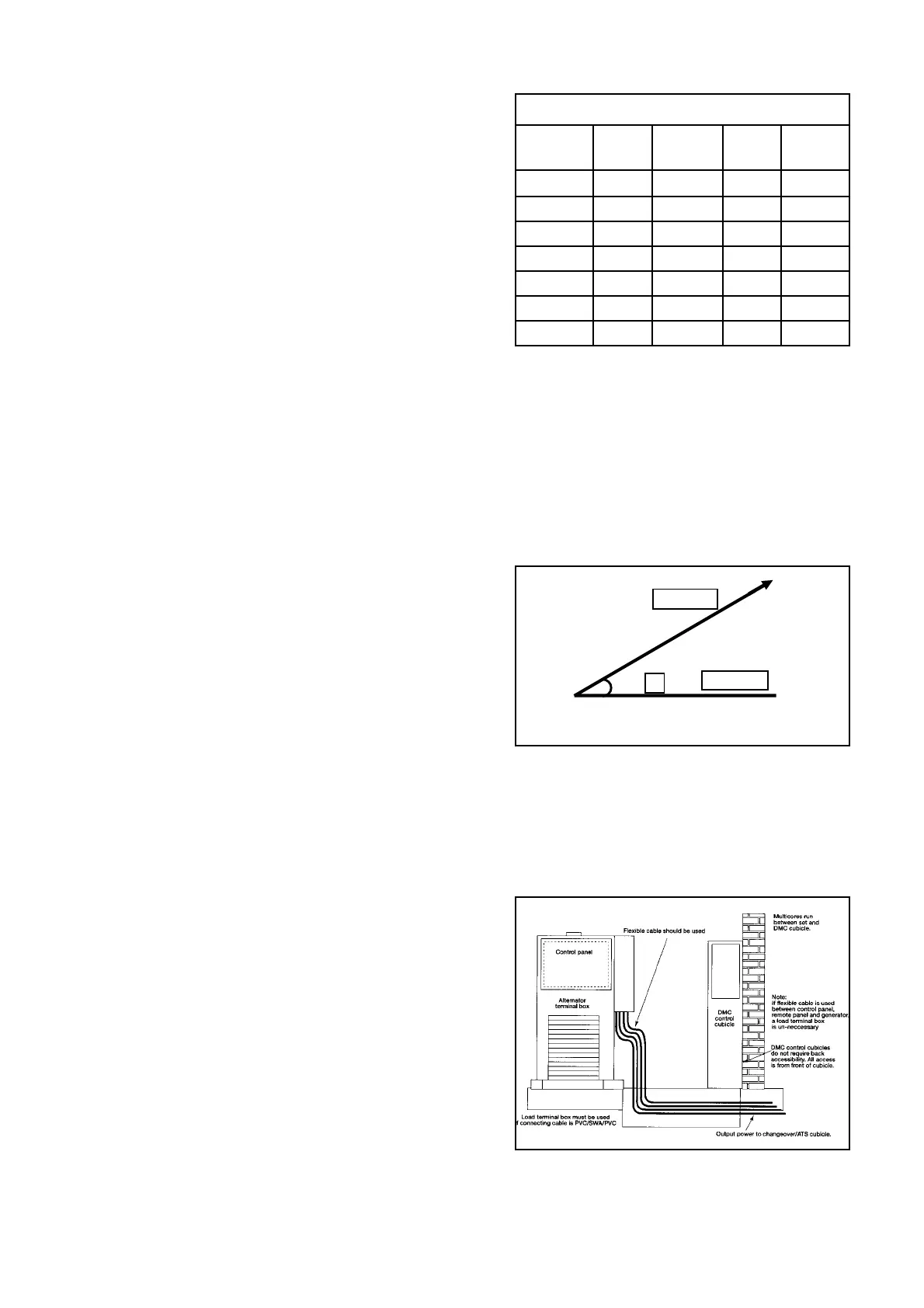
M Cabling
M.1 Always use flexible cables for inter connecting the
PCC3100 / PCC3200 controls with the switchgear and
other equipments.
M.2 Power cabling between alternator and control panel and
control panel and change over switch to mains should
be done with recommended cable sizes.
M.3 While terminating cables avoid any tension on the bolts /
busbars.
Ref. M.1
DETAILS FOR PCC1 (PCC 3100)
ENGINE KW FILE CT PART
MODEL Rating NAME RATIO NOS.
KTA50G8 1200 DFLF-50 4420/1 4084989
KTA50G3 1000 DFLC-50 3867/1 4084245
KTA38G5 800 DFJD-50 2839/1 4084175
KTA2300G 600 DFJB-50 2141/1 4084244
VTA28G5 500 DFGC-50 1893/1 4107379
VTA28G3 500 DFGC-50 1893/1 4107379
KTA19G4 400 DFED-50 1419/1 4104378
Ref. L.8
Ø