15
Ref. K.2
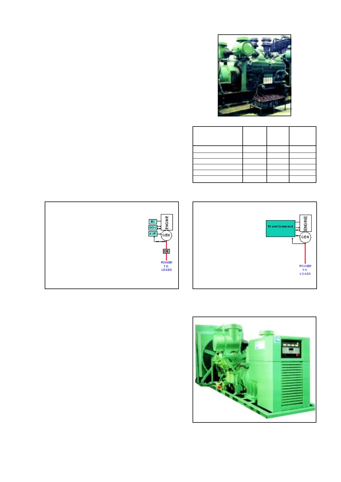
K Battery / Electrical System
K.1 Batteries supplied with genset are generally dry and
uncharged. First charging of uncharged batteries is very
important and should be done from authorised battery
charging center. It takes about 72-80 hours.
K.2 Batteries should be placed on stands and relatively at
cool place.
K.3 Please refer Table K.3 for battery capacity and cable
sizes for various engine models. Cable sizes are for
maximum length of 2 m. If length is more, size the
cable, so that voltage drop does not exceed 2V.
K.4 For AMF applications, a static battery charger working
on mains supply is recommended to keep the batteries
charged at all times.
L Genset / Engine Controls
The generator set is controlled locally by a dedicated
Generator Control Panel. This incorporates the control
systems, metering, alarm indications and customer
connections.
Two types of control system are currently available;
conventional and Power Command control.
L.1 Make sure that the polarity of the battery connections
are correct before applying power to the all Electronic
Controls.
L.2 Do not test wire leads to see if they are ‘live’ by flashing
them on either engine body or the ECP mounting stand.
L.3 Disconnect all connections to the control system on
engine / genset before doing any welding work on set.
L.4 There are no user serviceable parts inside the various
controls supplied along with Cummins engine / genset.
Call the nearest Cummins office / dealer for help.
L.5 Turn off or remove AC power from the battery charger
and then remove –ve battery cable from the engine /
genset battery. This will avoid possible PCB damage
and someone else starting engine / Genset accidentally.
L.6 Make sure the battery area is well ventilated before
servicing the battery. Arcing can cause explosion due
to hydrogen gas given off by batteries.
L.7 Always refer to the wiring diagram and product manual
supplied with the engine / genset for details.
Ref. K.3
Model Battery Cable Electrical
Capacity Size System
AH mm
2
Volts
KV and above 360 70 24
V28 / K19 180 70 24
N14/855/N8/C 180 50 24
B-5.9 150 50 12
S-3.8 120 50 12
X-Series 88 35 12
Genset with PCC
• Engine Control (EC)
– Protects Engine
– Starts/Stops Engine
• Governor (GOV)
– Controls Engine Speed/Frequency
• Voltage Regulator (AVR)
– Controls Output Voltage
• Circuit Breaker (CB)
– Protects Alternator, Feeder to Load
• Many Options
PLCs, AMF, Auto paralleling, synchronising
load sharing.
Power Command
• Single Control for all genset functions
– Governing
– Voltage Control
– Engine Control
– All Protection
– Advanced Control Functions
• Designed for the Genset Environment
– Vibration Tested
– Wide Variation in Ambient Temp.
– Dirty Environment
Conventional Control Power Command Control