18
Ref. P.3
Ref. O.2
Ref. O.3
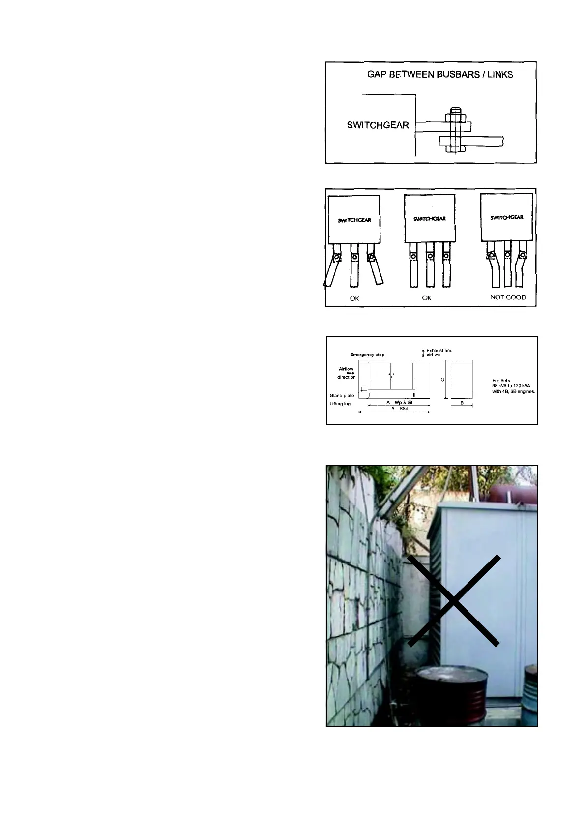
O.2 Gaps between busbars / links and terminals being
remedied by connecting bolt / stud (Ref. O.2). In such
cases the bolt will carry the load current. Normally these
bolts / studs are made of MS and hence are not
designed to carry currents.
O.3 Adequate clearance between busbars / links at terminals
should be maintained (IS:4232 may be referred to for
guidelines).
Ref. O.3 ranks the quality of different configurations.
Improper termination will lead to local heat generation
which may lead to failure.
P Genset with Acoustic Enclosure
Installation
P.1 Acoustic enclosures are supplied with built in AVMs.
As such genset can be installed directly on the leveled
surface.
P.2 Exhaust piping outlet should not be turned towards
window / ventilator of home or occupied building. Ensure
provision of rain cap.
P.3 The acoustic enclosure placement should be such that
there is no restriction in front of air inlet and outlet from
canopy.
Service Accessibility
P.4 Genset / Engine control panel should be visible from
outside the enclosure.
P.5 A / B / C check on engine / alternator (filter replacement
and tappet setting) should be possible without
dismantling acoustic enclosure.
P.6 For major repairs / overhaul, it may be required to
dismantle the acoustic enclosure.
P.7 Sufficient space should be available around the genset
for inspection and service.
General Design Guidelines
P.8 To avoid re-circulation of hot air, durable sealing between
radiator and canopy is must.
P.9 Sufficient capacity ventilation fans are required if radiator
fan flow is not sufficient. Please note that the fan flows
given in Table-1 are for open room installation. Fan flows
Typical Acoustic Enclosure Layout